Download
1 / 48
480 likes | 544 Views
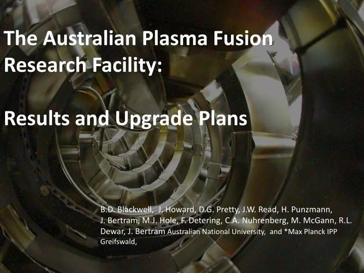
The Australian Plasma Fusion Research Facility: Results and Upgrade Plans.

E N D
The Australian Plasma Fusion Research Facility: Results and Upgrade Plans B.D. Blackwell, J. Howard, D.G. Pretty, J.W. Read, H. Punzmann, J. Bertram, M.J. Hole, F. Detering, C.A. Nuhrenberg, M. McGann, R.L. Dewar, J. BertramAustralian National University, and *Max Planck IPP Greifswald,
The Australian Plasma Fusion Facility: Results and Upgrade Plans Introduction H-1 Plasma and Facility Plasma configurations, parameters Facility Upgrade Aims Key areas New diagnostics for Upgrade Recent Results: MHD Modes in H-1 Data mining Alfvénic Scaling Optical Measurements Radial Structure Stellarator Fusion Recent Progress Reactor Considerations Conclusions/Future
H-1NF: National Plasma Fusion Research Facility A Major National Research Facility established in 1997 by the Commonwealth of Australia and the Australian National University Mission: • Detailed understanding of the basic physics of magnetically confined hot plasma in the HELIAC configuration • Development of advanced plasma measurement systems • Fundamental studies including turbulence and transport in plasma • Contribute to global research effort, maintain Australian presence in the field of plasma fusion power The facility is available to Australian researchers through the AINSE1 and internationally through collaboration with Plasma Research Laboratory, ANU. 1) Australian Institute of Nuclear Science and Engineering limited collaborative funding expires June 2010 – Canberra is only 3 hours away.
H-1 Heliac: Parameters 3 period heliac: 1992 Major radius 1m Minor radius 0.1-0.2m Vacuum chamber 33m2 excellent access Aspect ratio 5+ toroidal Magnetic Field 1 Tesla (0.2 DC) Heating Power 0.2MW 28 GHz ECH 0.3MW 6-25MHz ICH Parameters: achieved to date::expected n3e18 :: 1e19 T<200eV(Te)::500eV(Te) 0.1 :: 0.5%
H-1 Plasma Production by ICRF • ICRF Heating: • B=0.5Tesla, = CH (f~7Mhz) • Large variation in ne with iota Backward WaveOscillator Scanning Interferometer (Howard, Oliver) Axis
H-1 configuration (shape) is very flexible • “flexible heliac” : helical winding, with helicity matching the plasma, 2:1 range of twist/turn • H-1NF can control 2 out of 3 oftransform () magnetic well and shear (spatial rate of change) • Reversed Shear Advanced Tokamak mode of operation low shear = 4/3 = 5/4 medium shear Edge Centre
Santhosh Kumar Experimental confirmation of configurations Rotating wire array • 64 Mo wires (200um) • 90 - 1440 angles High accuracy (0.5mm) Moderate image quality Always available Excellent agreement with computation T.A. Santhosh Kumar B.D.Blackwell, J.Howard Iota ~ 1.4 (7/5)
The Australian Plasma Fusion Facility: Results and Upgrade Plans Introduction H-1 Plasma and Facility Plasma configurations, parameters Facility Upgrade Aims Key areas New diagnostics for Upgrade Recent Results: MHD Modes in H-1 Data mining Alfvénic Scaling Optical Measurements Radial Structure Stellarator Fusion Recent Progress Reactor Considerations Conclusions/Future
National Plasma Fusion Research Facility Upgrade Rudd Government’s “Super Science Package” Boosted National Collaborative Infrastructure Program using the “Educational Infrastructure Fund” Restrictions on this fund limit use to infrastructure ~$7M over 4 years for infrastructure upgrades 2009Australian Budget Papers Funding agreement to be signed this year Quarterly Milestones
Aims of Facility Upgrade Consolidate the facility infrastructure required to implement the ITER forum strategy plan Try to involve the full spectrum of the ITER Forum activities More specifically: • Improve plasma production/reliability/cleanliness • RF production/heating, ECH heating, baking, gettering, discharge cleaning • Improve diagnostics • Dedicated density interferometers and selected spectral monitors permanently in operation • Increasing opportunities for collaboration • Ideas? • Increasing suitability as a testbed for ITER diagnostics • Access to Divertor – like geometry, island divertor geometry
RF Upgrade • RF (7MHz) will be the “workhorse” • Low temperature, density limited by power • Required to initiate electron cyclotron plasma New system doubles power: 2x100kW systems. New movable shielded antenna to complement “bare” antenna (water and gas cooled). Advantages: • Very wide range of magnetic fields in Argon • New system allows magnetic field scan while keeping the resonant layer position constant.e.g. to test Alfven scaling MHD • Additional ECH source (10/30kW 14/28GHz) for higher Te
Improved Impurity Control Impurities limit plasma temperature (C, O, Fe, Cu) High temperature (>~100eV) desirable to excite spectral lines relevant to edge plasma and divertors in larger devices. Strategy : Combine - • Glow discharge cleaning for bulk of tank • Pulsed RF discharge cleaning for plasma facing components. • antenna (cooled) and source (2.4GHz) • Low temperature (90C) baking • Gettering – Titanium or Boron (o-carborane)
New Toroidal Mirnov Array View of plasma region through port opening Mounted next to Helical • Coils inside a SS thin-wall bellows (LP, E-static shield) • Access to otherwise inaccessible region with • largest signals and • with significant variation in toroidal curvature.
Small Linear Satellite Device – PWI Diagnostics Purpose: Testing various plasma wall interaction diagnostic concepts spectroscopy - laser interferometry - coherence imaging Features: Much higher power density than H-1 Clean conditions of H-1 not compromised by material erosion diagnostic tests Simple geometry, good for shorter-term students, simpler projects Shares heating and magnet supplies from H-1 Circular coils ex Univ Syd. Machines (“Supper II”) Magnetic Mirror/Helicon chamber? Mirror coils at one or both ends
Helicon H+ source Concept Based on ANU, ORNL work Gas Flow Water cooled target ne ~ 1019 m-3 m=+1 Helicon Antenna Directional Quartz/ceramic tube • Helicon Antenna is an efficient plasma source in Ar • High Density (>1018 m-3) more difficult in H • Combination of higher power and non-uniform magnetic field has produced ne ~ 1019 m-3in H Mirror Coils (Mirror coils at one end should be sufficient – mainly to provide field gradient rather than full mirror effect.)
Table from VanRooij 2008 Present and Future Plasma-Surface Devices H-1 Satellite Parameters comparable with best non-arcing devices - > 1MW/m2 with bias
Additional Power/Plasma Sources Sheath acceleration increases power density, but if >30-50V physical sputtering (not normal in fusion simulators, but may be useful to increase erosion?) E-beam can increase dissipation, but ion bombardment damage of LaB6 cathode if pressure too high?Solid LaB6 Cathode, >10A emission Sterling Scientific washer gun H+ 1019-1020 5-15eVunder the right conditions, can generatea relatively clean plasma (low W)denHartog: Plasma Sources Sci. Technol. 6 (1997) 492–498. (also useful for a simple way of obtainingfirst plasma) 15mm
Future Plasma Surface Interaction Facilities Magnum PSI Source: Cathode Cascaded plates Plasma source uses Resonant CX Ar+ +H2ArH+ +H dissociation, easier ionization Tests on this facility would be a logical next step following successful initial tests on the H1 Facility.
The Australian Plasma Fusion Facility: Results and Upgrade Plans Introduction H-1 Plasma and Facility Plasma configurations, parameters Facility Upgrade Aims Key areas New diagnostics for Upgrade Recent Results: MHD Modes in H-1 Data mining Alfvénic Scaling Optical Measurements Radial Structure Stellarator Fusion Recent Progress Reactor Considerations Conclusions/Future
Identification with Alfvén Eigenmodes: ne phase • Coherent mode near iota = 1.4, 26-60kHz, Alfvénic scaling with ne • m number resolved by bean array of Mirnov coils to be 2 or 3. • VAlfvén = B/(o) B/ne • Scaling in ne in time (right) andover various discharges (below) 1/ne ne f 1/ne Critical issue in fusion reactors: VAlfvén ~ fusion alpha velocity fusion driven instability!
Preprocessing(1): SVD Divide each time signal into 1ms pieces, then within these, Singular value decomposition “separates variables” time and space” for each mode 27/18 probe signals one time function (chronos) C(t) one spatial function (topos) T(x)Fmode = C(t) T(x) per mode (actually 2 or 3 in practice, sin-like and cos-like, travelling wave)
Preprocessing: SVDs grouped into “flucstrucs“ Singular value decomposition “separates variables” time and space” for each mode 27/18 probe signals one time function (chronos) C(t) one spatial function (topos) T(x)Fmode = C(t) T(x) per mode (actually 2 or 3 in practice, sin-like and cos-like, travelling wave) Group Singular Vectors with matching spectra > 0.7
D. Pretty Data Mining Classification by Clustering Full dataset
Identification with Alfvén eigenmodes: k||, twist Small near resonance Why is f so low? - VAlfven~ 5x10⁶ m/s • res = k||VAlfvén = k||B/(o) • k|| varies as the angle between magnetic field lines and the wave vector • for a periodic geometry the wave vector is determined by mode numbers n,m • Component of k parallel to B is - n/m k|| = (m/R0)( - n/m) res = (m/R0)( - n/m)B/(o) • Low shear means relatively simple dispersion relations – advantage of H-1 Alfvén dispersion (0-5MHz) Alfvén dispersion (0-50kHz) Near rationals, resonant freq. is low }
Identification with Alfvén eigenmodes: k||, iota = 4/3 ota res = k||VA = (m/R0)( - n/m)B/(o) • k|| varies as the angle between magnetic field lines and the wave vector k|| - n/m • iota resonant means k||, 0 Expect Fresto scale with iota Resonant
Overall fit assumingradial location Better fit of frequency to iota, ne obtained if the location of resonance is assumed be either at the zero shear radius, or at an outer radius if the associated resonance is not present. Assumed mode location ~ 5/4
Heliotron J (Kyoto): Good fits to m=2,3,4 in both senses(-ve B0 reversal)
Phase flips, character changes near rational • The sense of the phase between the magnetic and light fluctuations changes about the resonance • More “sound-mode” like. (red is ~ ne from visible emission ) • As k|| 0, || , so quasineutrality ion sound speed dominates Iota scanning in time
CAS3D: 3D and finite beta effects Carolin Nuhrenberg Gap forms to allow helical Alfven eigenmode, and beta induced gap appears at low f Beta induced gap ~5-10kHz Coupling to “sound mode”
John Howard, Jesse Read MHD: synchronous 2D imaging • Mirnov coil used as a reference signal. • PLL then matches the phase of its clock to the reference. • PLL output pulses drive the ICCD camera. • Delay output to explore MHD phase Performance Amplitude Time (s)
John Howard, Jesse Read Mode structure via synchronous 2D imaging • Intensified Princeton Instruments camera synchronised with mode using the intensifier pulse as a high speed gate. (256x256) • Total light or Carbon ion line imaged for delays of 0....1 cycle • Averaging is performed in the camera image plane, background removed by subtracting an unsynchronised shot. Intensity (arbitrary units) Toroidal Field Coils HelicalConductor
Interpretation Intensity Profile Amplitude (arbitrary units) • Images clearly show the mode’s helical structure. • Even parity, four zero crossings m ≥ 4. • Images at different time delays (between PLL pulse and camera gate) shows mode rotation. • Mode structure and rotation direction determined by comparing to a model. Vertical Position Profile segment line
John Howard, Jesse Read Mode Tomography Mode Model • Better to do the inverse problem • arbitrary radial profile, m=4, n=5 • Match sightline integrals with data • Use data from 18 different phases • Mode appears narrow in radius Data and reconstruction Result of asymmetry (plasma not central in camera view) Peaked at r/a ~0.7 Sin/coscpts Image (DC removed) Model (poloidal cross-section) 0.4 0.6 (r/a) 0.8 1.0
John Howard, Jason Bertram, Matthew Hole Alfvén Eigenmode structure in H-1 Compare cylindrical mode with optical emission measurements Test functions for development of a Bayesian method to fit CAS3D modes to experiment.
The Australian Plasma Fusion Facility: Results and Upgrade Plans Introduction H-1 Plasma and Facility Plasma configurations, parameters Facility Upgrade Aims Key areas New diagnostics for Upgrade Recent Results: MHD Modes in H-1 Data mining Alfvénic Scaling Optical Measurements Radial Structure Stellarator Fusion Recent Progress Reactor Considerations Conclusions/Future
Substantial progress over the last 3 decades • The three requirements: • temperature • density • confinement time LHD 2008 • For a fusion power plant, we need to improve the confinement time • Two ways to increase the confinement time: • Improve the effectiveness of the magnetic bottle • Make the device larger
Progress comparison to # CPU transistors per unit area on Si wafer ITER Fusion progress exceeds Moore’s law scaling
What about the last 15 years?…. • Politics of ITER agreement, cost • Advanced modes of tokamak operation • Eliminate transformer (necess. for continuous operation) • Disruption/Instability/ELM control • Compact tokamaks (Compass, NSTX, MAST) (Spherical tokamak for high beta) • Stellarators have made great progress • Performance parameters • Compact size (Aspect ratio halved) • Quasi-symmetry improves confinement
Stellarators break Tokamak barriers in density, twist and /(I/a.B0) Twist (1/qcylindrical)
Parameters achieved in the LHD Stellarator:2008 80x W7AS, 10 x short Neutral BeamInjection neETi~ 0.25 x10²⁰ ~ 40x short of Q~1
Stellarator Reactors: ITER successor? The Breakthrough (’80s) 3D MHD, and inverse problem, quasi-symmetry Garabedian, Nuhrenberg, Hirshman, Merkel, Dewar…… The Promise: Continuous operation(no transformer) No Disruptive Instabilities(no plasma current) Quasi-symmetry (good confinement) The Concept: ARIES CS: compact stellarator reactor PThermal: 2GW Radius: 8.3M Magnetic Field 14.4/5.3T
Stellarator Reactors: Challenge of Size F. NajmabadiUS/Japan Workshop on Power Plant Studies ARIES CS compact stellarator rea Fatter is better! Compact stellarator reduces size to comparable with advanced tokamaks
Stellarator Reactors: Challenge of Shape • Coils are not linked – allows removal for maintenance – but…. • Advanced Shape High Local Field • 14.4T for 5.3Tesla average field • Implications for superconductor material • Higher forces than tokamak – needs additional support tube • Insufficient room for blanket at “cusp” point – shield only
Conclusions • Large device physics accessible – e.g. Alfvénic modes observed • We show strong evidence for Alfvénic scaling of magnetic fluctuations in H-1, in ne, iota and . • The driving mechanism is not understood, unexplained factor of ~3 in the frequency • Interferometer and optical diagnostics (CCD camera and PMT array) valuable mode structure Information • First results are in qualitative agreement Stellarators as the step beyond ITER? • Promise of simple, continuous operation and stability • Challenge of size, shape and complexity • Tokamaks clearly better performers now, but stellarators catching up! • Recent LHD result - record density
Future • New Toroidal Mirnov Array • Bayesian MHD Mode Analysis • Toroidal visible light imaging (CII 525nm) • Correlation of multiple visible light, Mirnov and n~ e data • Spatial and Hybrid Spatial/Temporal Coherence Imaging • Facility upgrade! • Develop divertor and edge diagnostics • Study stellarator divertors, baffles e.g. 6/5 island divertor • Develop PWI diagnostics (materials connection) • Linear “Satellite” device for materials diagnostic development – multiple plasma sources, approach ITER edge