Download
1 / 22
380 likes | 1.75k Views
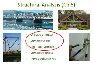
Today’s Objectives : Students will be able to: a) Draw the free body diagram of a frame or machine and its members. b) Determine the forces acting at the joints and supports of a frame or machine. Chapter 6 Structural Analysis Section 6.6 FRAMES AND MACHINES. READING QUIZ.

E N D
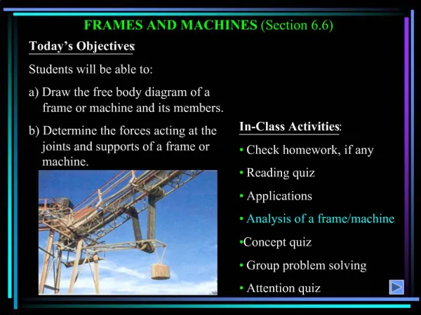
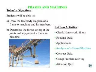
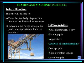
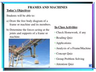
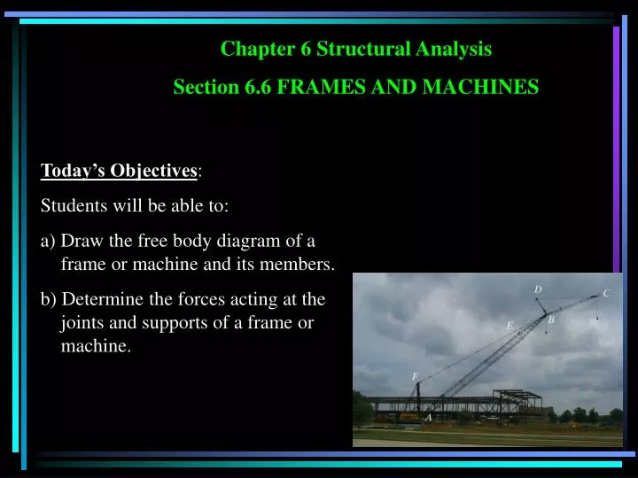
Today’s Objectives: Students will be able to: a) Draw the free body diagram of a frame or machine and its members. b) Determine the forces acting at the joints and supports of a frame or machine. Chapter 6 Structural Analysis Section 6.6 FRAMES AND MACHINES
READING QUIZ • 1. Frames and machines are different as compared to trusses since they have ___________. • A) Only two-force members B) Only multiforce members • C) At least one multiforce member D) At least one two-force member • 2. Forces common to any two contacting members act with _______ on the other member. • A) Equal magnitudes but opposite sense • B) Equal magnitudes and the same sense • C) Different magnitudes but opposite sense • D) Different magnitudes but the same sense
Frames are commonly used to support various external loads. APPLICATIONS How is a frame different than a truss? To be able to design a frame, you need to determine the forces at the joints and supports.
“Machines,” like those above, are used in a variety of applications. How are they different from trusses and frames? APPLICATIONS (continued) How can you determine the loads at the joints and supports? These forces and moments are required when designing the machine members.
Frames and machines are two common types of structures that have at least one multi-force member. (Recall that trusses have nothing but two-force members). FRAMES AND MACHINES: DEFINITIONS Frame Machine Frames are generally stationary and support external loads. Machines contain moving parts and are designed to alter the effect of forces.
STEPS FOR ANALYZING A FRAME OR MACHINE 1. Draw a FBD of the frame or machine and its members, as necessary. Hints:a) Identify any two-force members, b) forces on contacting surfaces (usually between a pin and a member) are equal and opposite, and, c) for a joint with more than two members or an external force, it is advisable to draw a FBD of the pin. FAB 2. Develop a strategy to apply the equations of equilibrium to solve for the unknowns. Problems are going to be challenging since there are usually several unknowns. A lot of practice is needed to develop good strategies.
Given: The frame supports an external load and moment as shown. Find: The horizontal and vertical components of the pin reactions at C and the magnitude of reaction at B. Plan: EXAMPLE a) Draw FBDs of the frame member BC. Why pick this part of the frame? b) Apply the equations of equilibrium and solve for the unknowns at C and B.
+ MC = FAB sin45° (1) – FAB cos45° (3) + 800 N m + 400 (2) = 0 FAB = 1131 N EXAMPLE 800 N m 400 N CX CY 1 m 1 m 2 m FBD of member BC B 45° FAB Please note that member AB is a two-force member. Equations of Equilibrium:
Now use the x and y direction Equations of Equilibrium: • + FX = – CX+ 1131 sin 45° = 0 CX = 800 N • + FY = – CY+ 1131 cos 45° – 400 = 0 • CY = 400 N EXAMPLE 800 N m 400 N CX CY 1 m 1 m 2 m FBD of member BC B 45° FAB
1. The figures show a frame and its FBDs. If an additional couple moment is applied at C, then how will you change the FBD of member BC at B? A) No change, still just one force (FAB) at B.B) Will have two forces, BX and BY, at B.C) Will have two forces and a moment at B.D) Will add one moment at B. CONCEPT QUIZ
CONCEPT QUIZ (continued) D 2. The figures show a frame and its FBDs. If an additional force is applied at D, then how will you change the FBD of member BC at B? A) No change, still just one force (FAB) at B.B) Will have two forces, BX and BY, at B.C) Will have two forces and a moment at B.D) Will add one moment at B.
Given: A frame supports a 50-kg cylinder. Find: The reactions that the pins exert on the frame at A and D. Plan: GROUP PROBLEM SOLVING a) Draw a FBD of member ABC and another one for CD. b) Apply the equations of equilibrium to each FBD to solve for the six unknowns. Think about a strategy to easily solve for the unknowns.
+ MA = CY (1.6) – 50 (9.81) (0.7) – 50 (9.81) (1.7) = 0 ; CY = 735.8 N Applying E-of-E to member ABC: GROUP PROBLEM SOLVING (continued) FBDs of members ABC and CD CY CX 50(9.81) N 0.7 m 1.2 m 1.6 m DX DY • + FY = AY– 735.8 – 50 (9.81) – 50 (9.81) = 0 ; AY = 245 N • + FX = CX– AX = 0 ; CX = AX
+ MD = CX (1.2) + 50 (9.81) (0.7) – 735.8(1.6) = 0 ; CX = 695 N Applying E-of-E to member CD: GROUP PROBLEM SOLVING (continued) FBDs of members ABC and CD CY CX 50(9.81) N 0.7 m 1.2 m 1.6 m DX DY • + FY = DY– 735.8 + 50 (9.81) = 0 ; DY = 245 N • + FX = DX– 695 = 0 ; DX = 695 N AX = CX = 695 N
1. When determining the reactions at joints A, B, and C, what is the minimum number of unknowns for solving this problem? A) 3 B) 4 C) 5 D) 6 ATTENTION QUIZ 2. For the above problem, imagine that you have drawn a FBD of member AB. What will be the easiest way to write an equation involving unknowns at B? A) MC = 0 B) MB = 0 C) MA = 0 D) FX = 0
Example 4: The 500 kg engine is suspended from the boom crane as shown. Determine resultant internal loadings acting on the cross section of the boom at point E.
Statics: Example 1 - Pliers Given: Typical household pliers as shown. Find: Force applied to wire and force in pin that connects the two parts of the pliers. . See solution Link Side: what is the shear stress in pin and bending stress in handle? SofM
Statics: Example 2 – Crane Structure Given: Crane structure as shown. Find: Forces and FBD’s for cables A-B and A-E, boom DEF and post AFC. See solution Link Side: what is the normal stress in cables (average normal only) and normal stress in boom and post (combined loading)? SofM
Example 3 (6.67) – Pulleys Determine the force P required to hold the 100 lb weight in equilibrium.
Example 4 (6.114) – Front End Loader Question 1: The tractor shovel carries a 500 kg load of soil having a center of mass at G. Compute the forces developed in the hydraulic cylinder BC and reaction forces at A due to this loading. Question 2: Compute the force at F (= force in link FH) and reaction forces at D.
Example 5 (6.115) – Clamping Device If a force of P = 100 N is applied to the handle of the toggle clamp, determine the horizontal clamping force Ne that the clamp exerts on the smooth wooden block at E.