Download
1 / 11
120 likes | 491 Views
KEEL. KEEL. TRIM TAB. AOE 3014 TAKE-HOME COMPUTER PROBLEM HONOR SYSTEM PLEDGE - NO AID GIVEN OR RECEIVED EXCEPT FOR PART 1 Part 1 DUE October 17, 2008; Parts 2- 7 DUE November 7, 2008

E N D
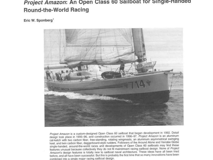
AOE 3014 TAKE-HOME COMPUTER PROBLEM HONOR SYSTEM PLEDGE - NO AID GIVEN OR RECEIVED EXCEPT FOR PART 1 Part 1 DUE October 17, 2008; Parts 2- 7 DUE November 7, 2008 The profile of the keel on the Project Amazon, an Open Class 60 sailboat for single- handed round- the-world racing, is shown in the figure below. The co-ordinates of this shape, which consists of a main element and a trim tab, are in the file AOE3014 Project Amazon Coord.doc on the website. Information on this shape is from: Sponberg, Eric W., Marine Technology, Vol. 37, No. 2, Spring 2000, pp.65 – 78, which is also on the website as AOE 3014 Project Amazon Sailboat.pdf The faired moveable trim tab permits a greater lift at low angles of attack, can quickly switch from one side to the other, and makes the boat point towards the wind much better. This thick wing section has many advantages over a thinner section: greater structural stiffness, larger angle of attack range before separation off of the leading edge (stall), larger angle of attack range with relatively low drag (“wide low drag bucket”), negligible increased drag, and more space to mount the trim tab. Thus, this thick wing section will keep flow attached better in waves and experience less speed loss due to stalling. Furthermore, the section interior is used as a fuel tank, which also increases the boat’s stability by having that weight lower than the hull. While we will not calculate the turbulent boundary layer and the separated flow, we will examine the inviscid pressure distribution that this profile produces at several angles of attack and trim tab positions.
We will use the vortex panel method (Kuethe and Chow, 5th Ed., pp. 156 – 164, AOE3014 Vortex Panel.pdf file on the website) with m panels on the body surface to calculate the flow. Note that you will need to use more panels near the nose, the trim tab joint, and tail in order to capture the expected variation of the pressure around the nose and tail. Also note that one must still use a sufficient number of straight panels over the lower surface curvature regions in order to capture the variation of the circulation distribution over the surface. Vortex panel codes written in several types of software are available on the course website.
Part 1. (5 points) To gain experience and confidence, as a test case run the NACA 2412 airfoil at 8 degrees angle of attack that is given in the AOE3014VortexPanel.pdf file on the website and submit a printout of correct results ON TIME - Oct. 17.You may work together to understand the code and get the code running, but you must pledge that you ran the test case yourself. All work below is for the Project Amazon keel profile. For m = 24 and for m = 48 calculate, plot, and discuss the following quantities for the angles of attack of α = 0o, 5 o, 10 o that are measured with respect to the line of symmetry of the main element. Use trim tab angles of β = 0o, 10o, 20 o . Thus, there are 9 possible cases to be investigated. YOU MUST PLEDGE THAT ALL OF THE WORK IS YOUR OWN WORK. Part 2. (40 points) Explore and discuss the effects of the number of panels used and their location, especially for the nose, trim tab joint, and tail regions. You must try at least 3 different paneling configurations for the 48 panel case with α = 10 o and β = 20 o . How sensitive are the lift results on the way panels are selected for the nose and the trim tab regions, including the location of the front stagnation point and the region around the joint between the main element and the trim tab? If there are oscillations in the resulting pressure distributions, adjust the panel locations and lengths to eliminate the oscillations.
Part 3. (10 points) Pressure coefficient Cp vs. X/C for the upper and lower surfaces of the keel hydrofoil for each case. Where does dCp/dX on the suction (upper) side become positive? What effect does a large positive dCp/dX have on the real viscous flow? Part 4. (4 points) Γ/CU versus α. (The total circulation Γ around the keel hydrofoil normalized on the chord C and the approach free-stream velocity U plotted as a function of the angle of attack.) You may need to add a few lines of code to compute the Γ. Part 5. (4 points) Lift coefficient Cl =l /qC (The lift per unit span l normalized on the approach free-stream dynamic pressure and the chord length vs. the angle of attack.) versus α for each β. What is the zero-lift angle of attack? Part 6. (8 points) Compare your lift coefficient results with thin airfoil theory for this problem. What is the effect of the finite thickness of this keel hydrofoil?
Part 7. Present your results, plots, and tabulated computer output in an organized report as if your employer would use them. Your employer requires that you explain what you did and what it means, without having to figure out what you did. The format should be the following. You should use a Table of Contents and give page numbers to help the reader find and understand your work. (4 points) A. Introduction: Briefly state the problem and the given information. (5 points) B. Description of the Solution Method: Briefly describe in your own words the mathematical and physical ideas that are in the vortex panel method that is used. C. Results from Parts 2-6: Describe the required results with tables and plots. Present labeled and understandable computer output for each of the cases that you run. (15 points)D. Discussion and Conclusions: Discuss the results and make conclusions about the usefulness of the results. Discuss the effect of the trim tab on the lift versus angle of attack results. How dependent are the answers on your selection of paneling? Which results are best? How large are the expected differences between your answers and answers obtained with many more panels? Are the answers more reliable in some parts of the keel shape than others? (10 points) E. Since you will have 5 weeks to work on this, the final 10 points will be given for thoroughness, organization, ease of reading the report, ability to find the answers in your work. Sloppy, difficult-to-read work that shows a minimal effort will not receive these points.