Download
1 / 12
120 likes | 224 Views
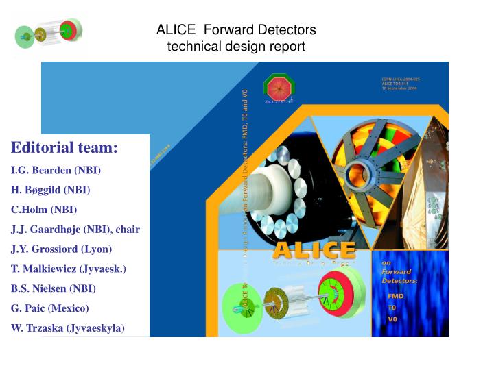
ALICE Forward Detectors technical design report. Editorial team: I.G. Bearden (NBI) H. Bøggild (NBI) C.Holm (NBI) J.J. Gaardhøje (NBI), chair J.Y. Grossiord (Lyon) T. Malkiewicz (Jyvaesk.) B.S. Nielsen (NBI) G. Paic (Mexico) W. Trzaska (Jyvaeskyla).

E N D
ALICE Forward Detectorstechnical design report Editorial team: I.G. Bearden (NBI) H. Bøggild (NBI) C.Holm (NBI) J.J. Gaardhøje (NBI), chair J.Y. Grossiord (Lyon) T. Malkiewicz (Jyvaesk.) B.S. Nielsen (NBI) G. Paic (Mexico) W. Trzaska (Jyvaeskyla)
Answers to LHCC Referees from FMD 31/1/2005 • Question 1: What are the plans for cooling optimisation of the FMD region? • Answer: • A first study of the temperature conditions in the FMD area (RB26) has indicated unacceptably high temperatures (in excess of 75 deg. C). General simulations of the temperature conditions in the ALICE central regions have been performed already and have led to an optimization of the cooling there. Detailed calculations in the FMD, TO, VO region, simulating varying airflow scenarios, are however not yet available. Work in this direction has started in January 2005 by the TS/CV group together with the ALICE infrastructure group. The outcome of these simulations will elucidate to what extent the problem can be solved by adequate flow/exhaust of cool dry air via dedicated ducts. The first results are expected by end February 2005. The FMD detectors only contribute with about 30 W on the RB 26 side. If air cooling should prove to be insufficient, active cooling of the mounting plates of the FMD detectors will be considered.
Answers to LHCC Referees from FMD 31/1/2005 • Question 2 : What is the status of the detector prototype building (expected early 2005 from table 4.10) • Answer: • Three prototype Si wafers have been ordered with Hamamatsu Photonics, Japan. Delivery date at NBI is listed as primo February 2005(*,see photos taken by Hamamatsu). The entire production of VA_ALICE preamplifier chips (500 units) has been completed by the IDEAS company (**), Norway. Tests indicate excellent performance with a noise level about 25 % lower than specified in the order to the company. The design of the hybrid board is completed and three prototypes have been delivered. Sample thin film pitch adapters, mounted on the hybrid boards to enable bonding to the Si-strips, have been tested for bonding strength at CERN with excellent results.. The bonding of prototypes (Si-sensors-to hybrids) has been agreed with the CERN bonding laboratory to commence shortly after delivery (~march). Subsequently test of the detector modules (sensor-FEE) will be tested with sources and high energy electron beams (ASTRID, ~april). • Concurrently a digitizer board is under development at NBI based on existing ALTRO technology. With the recently produced RCU card using USB readout this will allow a full test of the main part of the readout up to the summer of 2005.
FMD ’inner’ protype before dicing 2 sectors of 512 strips Test structures on 6” wafer
Some happy people playing with the RCU+TPC frontend card+USB+LAPTOP
Answers to LHCC Referees from FMD31/1/2005 • Question 3: Can you give more detailed information on the project planning and organisation than table 4.10, especially detailing all tasks and teams involved in the various labs, and interference between the tasks? • Answer: • The main hardware project (Si, FEE and Digitizer) is the responsibility of the Niels Bohr Institute group and its commercial suppliers. Many elements of the FEE (e.g. RCU, DDL and DAQ) hardware are based on element from other ALICE systems. The integration into a complete system is the responsibility of NBI. See below for a discussion of contribution of the Greek group to the FMD readout. The Russian group from INS has contributed primarily to the simulations in the TDR and is expected in the future to contribute to the development of analysis software.
Answers to LHCC Referees from FMD 31/1/2005 • Question 4: What are the present prospects for the Greek application to the project? • Answer: • Addendum #4 (CERN-RRB-2003-125) to the ALICE MoU, which re-defines the Greek contribution to ALICE construction, was signed by the Greek Funding Agency at the end of 2003. It defines a financial contribution of 100 kCHF to the forward detectors (FMD, T0, V0) and as particular responsibility DAQ read-out and online monitoring for all forward detectors. The participating Institute is the University of Athens (9 members), lead by Prof. Martha Stassinaki. • MoU addendum #4 : http://committees.web.cern.ch/Committees/LHCRRB/ALICE/CERN-RRB-2003-125.pdf • The group has installed in Athens a test setup of the ALICE DAQ system (DDL-SIU, DDL-DIU, DDL-Optical fibers, pRORC card, FEIC card plus a PC) and is currently working on software for read-out and monitoring tasks for the forward detectors. • Additional responsibilities of Athens include the control system for the TPC grid pulser and participation in the TRD HV and DCS systems (for a total of 110 kCHF).