Download
1 / 27
270 likes | 362 Views
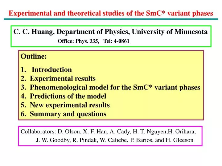
Experimental and theoretical studies of the SmC* variant phases. C. C. Huang, Department of Physics, University of Minnesota Office: Phys. 335, Tel: 4-0861. Outline: Introduction 2. Experimental results 3. Phenomenological model for the SmC* variant phases 4. Predictions of the model

E N D
Experimental and theoretical studies of the SmC* variant phases C. C. Huang, Department of Physics, University of Minnesota Office: Phys. 335, Tel: 4-0861 • Outline: • Introduction • 2. Experimental results • 3. Phenomenological model for the SmC* variant phases • 4. Predictions of the model • 5. New experimental results • 6. Summary and questions Collaborators: D. Olson, X. F. Han, A. Cady, H. T. Nguyen,H. Orihara, J. W. Goodby, R. Pindak, W. Caliebe, P. Barios, and H. Gleeson
Conventional molecular arrangements in the SmA and SmC phases In 1975, R. B. Meyer et al., proposed and synthesized the following chiral compound that displays ferroelectric response in the SmC* phase. Spontaneous polarization is perpendicular to the tilt plane. DOBAMBC SmC*
Two unique physical properties associated with the SmC* phase Sample: DOBAMBC, Tc : SmA-SmC* transition temperature Spontaneous polarization Saturation polarization 60 mC/m2 Helical pitch
Compounds with large spontaneous polarization In 1989, A. D. L. Chandani et al., (Jpn. J. Appl. Phys. Part 2 28, L1265) reported the discovery of antiferroelectric response from the following compound: MHPOBC Saturation polarization> 500 mC/m2.
Thermal studies of MHPOBC sample Refs: A. D. L. Chandani, et al., Jpn. J. Appl. Phys. 28, L1261 (89). K. Ema, et al., Phys. Rev. E 47, 1203 (93).
Chiral tilted smectic phases ? q z ? y ? x c f
Sequence of SmC* variance phases and their preliminary properties By employing various electro-optical techniques to study these phases, the following properties have been obtained: Upon Cooling: SmCa* phase: uniaxial phase SmC* phase AF or SmCFI2* phase: 4-layer structure SmCg* or SmCFI1* phase: 3-layer structure SmCA* : 2-layer structure SmCFI2* SmCFI1* SmCA* Ref.: T. Matsumoto, et al., J. Mater. Chem. 9, 2051 (1999).
Fluorescence spectrum from a 10OTBBB1M7 powder sample Sample: 10OTBBB1M7
Polarization-analyzed resonant x-ray results from SmC* variant phases p Sample: 10OTBBB1M7 p n = 5 to 8 SmCa* p p SmCFI2* s ruled out proposed n = 4 Intensity (Counts/5 seconds) p p SmCFI1* n = 3 p SmCA* n = 2 Ref: P. Mach et al., PRL 81, 1015 (98). Qz/Qo
X-ray scattering intensity in the vicinity of the resonant energy Eo = 2474.8 eV In the SmCFI2* phase Sample: 10OTBBB1M7
Ellipsometry results from the SmCFI2* phase of MHDDOPTCOB Employ a powerful ellipsometer specially designed by our research group proposed ruled out T = 82.51 °C Fitting parameters: d =35.07Å q= 31.0° ne= 1.645 no= 1.485 d= 18° Ref. : P. M. Johnson, et al. PRL 84, 4870 (2000).
High-resolution resonant x-ray scattering results Sample: MHDDOPTCOB Ising Model: two equal intensity split peaks Clock Model: single peak Distorted Model: Split peaks with different intensity intensity ratio distortion angle separation size of helical pitch The measured distortion angle (d2 =15) in good agreement with our optical result which yielded d2 =18. SmCFI2* Ref: A. Cady et al., Phys. Rev. E (RC) 64, 05702 (2001)
Experimental Results Experimental advances by resonant x-ray diffraction and optical studies 1. SmCa*: incommensurate short-helical pitch with pitch size > 4 layers (1999) 2. SmCFI2*: distorted 4-layer structure (2000, 2001) 3. SmCFI1*: distorted 3-layer structure (2000) SmCa* SmCFI2* SmCFI1*
Theoretical advances: phenomenological approach 1. M. Yamashita and S. Miyazima, Ferroelectrics 48, 1, (1993). Ising-like structure 2. A. Roy and N.V. Madhusudana, Europhys. Lett. 36, 221 (1996). Uniform helical phases and a non-uniformly modulated phases 3. M. Skarabot et al., Phys. Rev. E 58, 575 (1998). Short helical pitch and bi-layer structures 4. S. Pikin et al., Liq. Cryst. 26, 1107 (1999). Short helical pitch structures 5. M. Cepic and B. Zeks, Phys.Rev. Lett. 87, 85501 (2001). Short helical pitch structures None of them predicts the stability of distorted 3- or 4-layer structures.
Phenomenological model for the SmC* variant phases The molecular tilt in k-th layer can be described by xk = q(cos(fk), sin(fk)). Chiral: the simplest chiral term is f1(xk x xk+1) Phenomenological model: one with a minimum number of expansion terms which yields all the observed SmC* variant phases and offers new predictions. The description of observed SmC* variant phases (ignore the long optical helical pitch): SmC*: ferroelectric phase SmCA*: antiferroelectric phase SmCFI1*: distorted structure with a 3-layer unit cell SmCFI2*: distorted structure with a 4-layer unit cell SmCa*: incommensurate nano-scale helical pitch structure with pitch size > 4 layers z q y fk x
Various interlayer coupling terms A) n.n. coupling term: a1(xk .xk+1) a1 < 0 ferroelectric coupling a1 > 0 anti-ferroelectric coupling B) 3-layer unit cell: requires 3rd n.n. coupling term: a3(xk .xk+3) and a3 < 0 C) Thus the free energy expansion can be written as: G = [a1(xk .xk+1) + a2(xk .xk+2) + a3(xk .xk+3) + f1(xk xxk+1)] D) Do we need 4th n.n. coupling term to describe SmCFI2* with a 4-layer unit cell? The key feature for SmCFI2* is that n.n.n. orientation is anti-clinic. Thus this requires that a2 > 0 as well as both a1 and a3 are not too large. k Simulation results: f1 0, leads to simple helical structures and no well-defined phases with 3- or 4-layer unit cell and is similar to Cepic’s approach.
The final free energy which yields the all the observed phases One crucial additional term: b(xk .xk+1)2 Thus: G = [a1(xk .xk+1) + a2(xk .xk+2) + a3(xk .xk+3) + f1(xk xxk+1) + b(xk .xk+1)2] b > 0 bi-layer model which has been considered previously b < 0 stable 3- and 4- layer distorted unit cell. We are mainly interested in minimizing the free energy G for various molecular azimuthal orientation with a given set of coefficients: a1, a2, a3, f1, and b. It is expected that a1 and a2 are the two most important ones. Thus for a given set of parameters (a3, f1, and b), we have identified the following phase diagram as a function of a1 and a2. k
Phase diagram generated by the phenomenological model a3 = -0.07K, f1 = 0.12 K bq2 = -0.2K SmCd3* and SmCd4*: 3- and 4- layer distorted structure. SmCa1* and SmCa2*: INHP structure with pitch > 4 and < 4 layers a2 < 0 n.n.n. synclinic a1 < 0 SmC* a1 > 0 SmCA* a1 0, a2 0 and a3 < 0 SmCd3* a2 > 0 n.n.n. anticlinic small a1 SmCd4* a2 - a1 SmCa1* a2 a1 SmCa2* Ref: D. A. Olson, X. F. Han, A. Cady, and C. C. Huang, PRE 66, 021702 (2002).
Pitch evolution along two different paths SmCa1* SmC* a) pitch versus a2 along the path 1 for the SmCa1*-SmC* transition. b) pitch versus a1 along the path 2 for the SmCa1*-SmCd4*- SmCa2* transition. Pitch length (layers) SmCa2* SmCd4* SmCa1*
Optical rotatory power vs. temperature from two compounds 11OTBBB1M7 10OTBBB1M7 no pitch inversion within the SmCFI2* phase window pitch inversion Ref: F. Beaubois, et al., Eur. Phys. J. E 3, 273 (2000).
The distortion angle (d) in 4- and 3-layer distorted phases a3 = -0.07K, f1 = 0.12 K bq2 = -0.2K In the SmCd4*, darcsin(- f1/(2 bq2)) if pitch length is large.
Temperature variation of pitch (> 4 layers) from two compounds a) The helical pitch of 10OTBBB1M7 decreases monotonically on cooling through the SmCa* phase as measured using resonant x-ray diffraction by P. Mach et al., Phys. Rev. E 60, 6793 (1999). b) A much different helical pitch evolution in MHR49 as measured using resonant x-ray diffraction by L. S. Hirst etal., Phys. Rev. E 65, 041705 (2002).
Pitch evolution in MHPOCBC A new SmCa* phase with pitch < 4 layers is experimental found by an optical probe! Layer thickness 3nm Laser wavelength = 630nm. SmCa* SmCA* Ref. A. Cady et al., PRL 91, 125502 (2003).
Summary 1. Our phenomenological model with five expansion terms has given theoretical support to the existence of the SmCd3* and SmCd4* with 3- and 4- layer distorted structures. Question Can the SmCd3* and SmCd4* fully describe the corresponding SmCFI1* and SmCFI2* phases? More research work needs to be done to answer the question. At least, the predicted helical pitch inversion in the SmCFI2* phase has been observed in one liquid crystal compound. 2. The model also predicts the existence of the SmCa2* phase with pitch less than four layers. Experimentally we have shown the existence of such a phase. Question Some critical properties of the SmCa2* phase have to be experimentally tested. Related work is in progress. 3. The proposed model may not be the complete one. On the other hand, it contains the minimum number of terms to yield the stability of all observed SmC* variant phases. Definitely, it will form the starting point for the future theoretical modeling for the SmC* variant phases.
Phase sequences upon cooling SmA –SmCa1*-SmC*-SmCFI2*-SmCFI1*-SmCA*
Additional questions • With liquid-like molecular arrangements within each layer, • what are the physical origins of the next-nearest-neighbor • and the 3rd nearest neighbor interactions, required for this • phenomenological model? • Recently, M. B. Hamaneh and P. L. Taylor (PRL, in press) • have offered one plausible explanation. • 2. At least, two theoretical models have predicted the stability of • a phase with the six-layer structure. So far, there is no experimental • support of such a six-layer structure. Can a phase with the six-layer • structure be stable in our simple model? • a2 (xk. xk+2) + b(xk.xk+1)2 four- layer structure • a3(xk.xk+3) + b(xk.xk+1)2? Research work is supported by NSF, PRF, and DOE through BNL