Download
1 / 57
580 likes | 764 Views
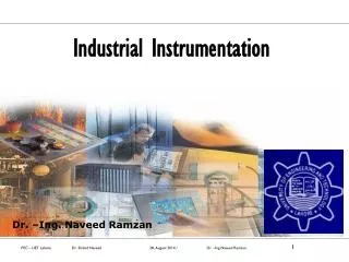
Industrial Instrumentation. Dr. –Ing. Naveed Ramzan. Pressure Sensors. “In any given plant, the number of pressure gauges used is probably larger than all other instruments put together”. Practical Considerations in Pressure Measurements.

E N D
Industrial Instrumentation Dr. –Ing. Naveed Ramzan
Pressure Sensors “In any given plant, the number of pressure gauges used is probably larger than all other instruments put together”
Practical Considerations in Pressure Measurements • In industrial applications, good repeatability often is more important then absolute accuracy. • If process pressures vary over a wide range, transducers with good linearity and low hysteresis are the preferred choice. • Ambient and process temperature variations also cause errors in pressure measurements, particularly in detecting low pressures and small differential pressures. In such applications, temperature compensators must be used
Practical Considerations in Pressure Measurements • Selection Criteria • Pressure transducers usually generate output signals in the millivolt range (spans of 100 mV to 250 mV). When used in transmitters, these are often amplified to the voltage level (1 to 5 V) and converted to current loops, usually 4-20 mA dc. The transducer housing should be selected to meet both the electrical area classification and the corrosion requirements of the particular installation. • If the installation is in an area where explosive vapors may be present, the transducer or transmitter and its power supply must be suitable for these environments. This is usually achieved either by placing them inside purged or explosion proof housings, or by using intrinsically safe designs. • The single most important decision in selecting a pressure transducer is the range • When high process temperatures are present, one can consider the use of various methods of isolating the pressure instrument from the process. These include loop seals, siphons, chemical seals with capillary tubing for remote mounting, and purging.
Practical Considerations in Pressure Measurements Maintenance Without exception, pressure sensors require scheduled, periodic maintenance and/or recalibration.
Practical Considerations in Pressure Measurements • Calibration • Pressure transducers can be recalibrated • 1. on-line or • 2. in a calibration laboratory. • Laboratory recalibration typically is preferred, but often is not possible or necessary. • In the laboratory, there usually are two types of calibration devices: • deadweight testers that provide primary, base-line standards, and • laboratory or field standard calibration devices
Question No. 1 • The difference between gauge and absolute pressure is • a Vacuum • 0.433 psia • atmospheric pressure • zero
Question No. 2 • Pressure is defined as • Force per unit area • F. A • A/F • None of the above
Question No. 3 • Metals used in the bourdon tubes should not undergo • Fatigue • hysteresis • creep • All of the above
Question No. 4 • A capsule diaphragm is made by welding two diaphragms • to a solid base • together at the center • together around the edges • To two other diaphragms
Question No. 5 • Dead weight tester is used for • testing dead weights • measuring process pressures accurately • producing high pressure • calibrating pressure instruments
Question No. 6 • One torr is defined as • One mm Hg • One inch Hg • One atmosphere • One kilopascal
Question No. 7 • Which gauge measures pressure by sensing changes in the thermal conductivity of the gas • Pirani gauge • Slack diaphragm gauge • Mcleod gauge • None of them
Question No. 8 • A thermocouple gauge is one type of • Ionization gauge • Thermal conductivity gauge • Mcleod gauge • None of these
Question No. 9 • Diaphragms used in pressure applications are • light • Small in size • slack • bimetallic
Question No. 10 • A Mcleod gauge can measure pressure as low as • 0.05 torr • 0.005 torr • 0.0005 torr • 0.00005 torr
Question No. 10 • What type of manometer is best for measuring low pressures • Well • Inclined • U-Tube • Multiple tube
Question No. 11 • A capacitance pressure transducer indicates changes in pressure by changing the • Voltage output of an ac circuit • frequency • capacitance • alternating current
Home Work Make similar 5 MCQs from Temperature and Pressure Sensors by each member. Solve Them and attached the sheet
A Quick View! What we have covered? Total Lectures held 9 • Fundamentals of Electrical Technology and digital logic employed in the measurement • Review of Scientific principles employed in instruments • Parts of Instrument • Performance Characteristics of Instruments • Selection and Calibration of Instruments • Instruments Identification and Line Symbols • Principle measurements desired in industry (a) Temperature (b) Pressure, Load (c) Level (d) Flow (e) Others ( Weight, Composition, pH etc.) (f) Transducers • Installation and Installation Costs • Case Studies Quiz Held = 1 : Next Test due on = 19-10-2010 Assignment due on 2-11-2010 Marks : 20
Level Measurement Level is another common process variable that is measured in many industries. The method used will vary widely depending on the nature of the industry, the process, and the application. • Inventory: • -- a constant supply or storage of material • Control: • -- continuous, batch, blending, and mixing control • -- stabilize flow to the next process • Alarming: • -- hi/lo limits, safety shut down • Data Logging: • -- material quantities for inventory and billing purposes and where regulatory requirements are necessary
What is measured? The measured medium can be liquid, gas or solid and stored in vessels (open/closed tanks), silos, bins and hoppers. Units of level can be expressed in: • feet (meters) • gallons (liters) • pounds (kilograms) • cubic volume (ft3, m3)
Methods ---- Direct or Indirect (inferential) • Hydrostatic Head • Float • Load Cells • Magnetic Level Gauge • Capacitance Transmitters • Magnetostrictive • Ultrasonic • Microwave • Laser • Radar • Guided Wave Radar • Dip Stick • Vibration
Direct Methods Direct methods sense the surface or interface of the liquid and is not affected by changes in material density (Specific Gravity) Examples: • Dip Stick • Resistance Tapes • Sight Glass • Floats • Ultrasonic
Indirect Methods (Inferential) Indirect methods “infer” liquid level by measuring some other physical parameter such as pressure, weight, or temperature. Changing materials means a corrective factor must be used or recalibrating the instrument. Examples: • Hydrostatic head methods • Load Cells • Capacitance • Conductivity
Selection Criteria When determining the type of level sensor that should be used for a given application, there are a series of questions that must be answered: • Open tank or closed tank? • Can the level sensor be inserted into the tank or should it be completely external? Contact or non-contact? • Continuous measurement or point measurement? • Direct or Indirect measurement? • What type of material is being measured? Liquid or Solid? Clean or Slurry?
Selection Criteria For all liquids you will need: • The system operating temperature with max. and min. excursions? two wide range – expensive the sensor • The system operating pressure? • Check that system ‘T’ and ‘P’ do not conflict with the materials of construction?
Selection Criteria For Solids: • Bulk density Be careful with very large silos as compaction at the bottom can greatly change assume bulk densities • Flow characteristics? • Expected particle size distribution? • Is solid abrasive and/or corrosive and what is the moisture/solvent content?
For Liquids Dip Stick • Simple and cheap • Can be used with any wet material and not affected by density. • Can not be used with pressurized tanks • Visual indication only (electronic versions are available) RodGauge - similar to a dipstick found in a car, it has weighted line markings to indicate depth or volume
For Liquids Sight Glass Another simple direct method of measuring liquids. Can be used in pressurized tanks (as long as the glass or plastic tube can handle the pressure) Good for applications where non-contact measurement is needed (like beverages)
For Liquids Floats Float rides the surface level to provide the measurement. Many different styles are available. Usually used for pump control, high/low level alarms and emergency shut-off Liquid density does not affect measurement
For Liquids Conductivity Level Measurement Point Level Measurement Continuous Level Measurement • Advantages and disadvantages • Low Cost • Conductive, non-coating liquids only • Insulating coatings can cause problems
For Liquids Resistance Tape The pressure of the fluid in the tank causes the tape to short-circuit, thus changing the total resistance of the measuring tape. An electronic circuit measures the resistance; it's directly related to the liquid level in the tank.
For Liquids Instrument input does not matter P Regulated purge system (air or nitrogen) Bottom of tube determines reference point Bubblers Bubblers allow the indicator to be located anywhere. The air pressure in the tube varies with the head pressure of the height of the liquid. Can’t be used in closed tanks or where purging a liquid is not allowed (soap). Very popular in the paper industry because the air purge keeps the tube from plugging.
For Liquids Instrument input does not matter P Regulated purge system (air or nitrogen) Bottom of tube determines reference point Bubblers Advantages: -- Easy installation -- Continuous reading providing analogue or digital signal -- No moving parts -- Good accuracy and repeatability
For Liquids Instrument input does not matter P Regulated purge system (air or nitrogen) Bottom of tube determines reference point Bubblers Limitations: -- Not suitable for pressurized tanks -- Sediments may block tube or probe -- Tanks must be freely vented
Hydrostatic Head Level Sensors • These methods infer level by measuring the hydrostatic head produced by the liquid column. • A pressure sensing element is installed at the bottom of the tank and pressure is converted to level. • Different liquid densities or closed tank applications must be accounted for.
Hydrostatic Head Level Sensors Liquid Density (D) Height (H) Pressure PSI General Theory for Head Measurement The Pressure exerted by the Height of the liquid is: P = H x Density* If the Density of the liquid is known then H = Pressure Density* *Note: For liquids other than water, use the density of water 0.0361 lb/in3 as a reference and multiply by the SG of the liquid.
Water Density (D) Oil Density (D) Height (H) Height (H) Tank 1 PSI Tank 2 PSI Example A dip stick measurement of the level of these 2 tanks indicates 30 feet of liquid in both tanks. Calculate the pressure that each gauge will read if tank 1 contains water (S.G. = 1) and tank 2 contains oil (S.G. = 0.85) P = ? psi P = ? psi
Water Density (D) Oil Density (D) Height (H) Height (H) Tank 1 PSI Tank 2 PSI Example A dip stick measurement of the level of these 2 tanks indicates 30 feet of liquid in both tanks. Calculate the pressure that each gauge will read if tank 1 contains water (S.G. = 1) and tank 2 contains oil (S.G. = 0.85) P = ? psi P = H x Density = 30 ft x 0.0361 lbs/in3 = (30 x 12) x 0.0361 = 13 psi
Water Density (D) Oil Density (D) Height (H) Height (H) Tank 1 PSI Tank 2 PSI Example A dip stick measurement of the level of these 2 tanks indicates 30 feet of liquid in both tanks. Calculate the pressure that each gauge will read if tank 1 contains water (S.G. = 1) and tank 2 contains oil (S.G. = 0.85) P = H x Density x SG = 30 ft x 0.0361 lbs/in3x 1 = (30 x 12) x 0.0361 = 13 psi P = H x Density x SG = 30 ft x 0.0361 lbs/in3x 0.85 = (30 x 12) x 0.0361 x 0.85 = 11 psi
Hydrostatic Head Level Sensors (Cont‘d) Liquid Density (D) Height (H) Pressure PSI Liquid Density (D) Height (H) Pressure PSI Practical Considerations when using head type instruments The reference point of the tank vs instrument input must be considered. This may not be practical in some applications where the tank elevation is below grade or where a remote visual reading is required.
Hydrostatic Head Level Sensors (Cont‘d) Water Density (D) Height (H) P P Tank Elevations Vertical rises and drops contribute to the overall height and therefore head pressure. Horizontal runs have no effect.
Hydrostatic Head Level Sensors (Cont‘d) P (atmospheric) P Head = h x D P vapour P Head = (h x D) + P vapour Closed Tank Applications Open tanks are vented to atmosphere so the pressure at the bottom of the tank is only due to the head pressure of the liquid. Closed tanks are not vented to atmosphere so the pressure at the bottom of the tank is due to the head pressure of the liquid + the vapour pressure above the surface.
Magnetic Level Sensor Used where the sight glass level gauge can not be used. Magneto-resistive types can provide an electrical output. Liquid/liquid interface (such as water and oil) can be measured by changing the buoyancy of the magnetic float
Displacers • Not the same as a float. • The displacer is immersed in the tank and the buoyant force of the liquid produces a torque which is proportional the amount of liquid level. The output force can be converted to provide a proportional pneumatic or electrical continuous output of tank level.
Displacers Displacer – side mounted unit The displacer float size and diameter is selected according to the size of tank and the height of the level to be measured. The output force can be converted to provide a proportional pneumatic or electrical continuous output of level. Advantages and disadvantages: • Very little movement of displacer float • Affected by different liquid densities • Limited to smaller tanks sizes
UltraSonic Level Measurement • Non-Contact direct level sensor • Level is a function of the time it takes an ultrasonic pulse to hit the surface and return • Limitations include: • Surface foam absorbs signal, agitation create reflections • High Pressure & High Temperatures affect the signal speed • Vapour and condensate create false echo’s