Download
1 / 30
300 likes | 400 Views
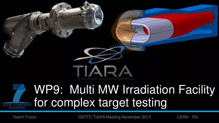
WP9: Multi MW Irradiation Facility for complex target testing . Yoann Fusco DSTFC TIARA Meeting November 2013 CERN - EN. TIARA WP9.1 Team Members. Masoud Berzhad SKKU Target CFD Sebastien Bousson CNRS WP 9 leader Yoann Fusco CERN Design & analysis

E N D
WP9: Multi MW Irradiation Facility for complex target testing Yoann Fusco DSTFC TIARA Meeting November 2013 CERN - EN
TIARA WP9.1 Team Members • MasoudBerzhad SKKU Target CFD • SebastienBousson CNRS WP 9 leader • Yoann Fusco CERN Design & analysis • YacineKadi CERN, SKKU WP 9.1 leader • Raul Luis ITN Neutronic calculation • Yuri Romanets ITNNeutronic modeling • Karel Samec CERN Engineering responsible
WP9.1 Summary description • WP9 Task 1: TIHPAC : Test Infrastructure for High Power Accelerators Components • The objective of this Work Package is to coordinate the design of a test infrastructure corresponding to an irradiation test facility for high power target developments
Publications and conferences • WP9.1 participation in conferences leading to a number of publications, outside EU reporting
Design process • Iterative process starting with a specification from the prospective client needing to test materials under: • At least 10 Dpa per year • up to 600°C • up to 500 Mpa (static or cyclical) • Liquid metal corrosion • Facility must be useable “anywhere” • Integrated safety barriers, no need for dedicated zone
Overall Concept • Entire facility is an easily transportable truss with rollers / airpads, containing irradiation area and all ancillaries, barriers and shielding • In the center of the facility rests the neutron spallation source where the material samples are positioned for testing The spallation source contains liquid lead which when hit by a proton beam emits neutrons thus leading to dpa build-up in samples from neutrons and protons • A primary loop interfaces with a secondary loop containing gallium which then evacuates the heat to an air-cooled heat exchanger
Tiara Target station concept Conical beam window optimized for flattened elliptical beam cross-section PROTON BEAM
Tiara Target station concept Sample holder Cusp-shaped beam window PROTON BEAM
Tiara Target station concept Outflow PROTON BEAM Inflow
Detail of Samples loading Liquid metal flow over samples
Detail of Samples loading LM flow Stress analysis on sample loading mechanism
CFD Analysis of Target • Analysis identified some need for improvement. Thus annulus was lengthened by an additional 10 cm to allow equal distribution of velocity field in test area. • Shielding studies showed the need to implement stronger shielding at rear of target, leading to new design of inlet/outlet connection • New CFD of modified target is needed, however no difficulties anticipated. Not a priority in 2013.
Novel Heat Exchanger • A primary fluid circulating in a central tube (blue) is located inside a hollow cylinder forming a spiral flow containing the secondary fluid (orange) • The inner primary pin can easily be extracted from the secondary cylinder, thus ensuring the two fluids are kept separate (no leak-through) and can be sent for maintenance in different zones
Novel Heat Exchanger /2 • The primary hotter fluid reverses at the end of the central pin and exits from the same side • The secondary fluid travels in a spiral around the primary container and is in contact with it through a double-wall which serves as an extra barrier but does degrade the performance • The design is nevertheless able to evacuate 100 kW in a very compact design
Primary Loop Design • Design allows certain minimal functions to be performed such as: • Drainage: full redundancy and external evacuation • On-line Filtering on bypass line • Large pressurizer able to also collect spallation gases • Detachable primary/secondary HEX interface • HEX bypass for thermal control • All control valves manual/pneumatic
Secondary Loop Design • Secondary loop fits inside a detachable truss located inside the primary truss, from which it is distinct • Heat evacuation by air heat exchanger using forced heat convection to dump heat to laboratory • Pump using permanent magnet and conventional motor (diversity + ease of maintenance) • Interface with primary limited to barrel of heat exchanger sliding over primary pin
Neutronics Analysis • Neutronics analysis in terms of shielding to allow ease of maintenance. Space is limited but should be sufficient • DPA analysis of samples, Optimization of reflectors to concentrate hard spectrum flux inside a limited volume • DPA and heat deposition analysis of window leading to stress analysis and lifetime prediction (~ end of December 2013)
Neutronics Analysis / 2 – Power Deposition (W/cm3) • Very detailed model allowing great depth of investigation into every aspect of the design.
Neutronics Analysis / 3 – Sample Analysis • DPA values up to 0.4 DPA/month • Relative contribution from protons and neutrons depends on the position of the sample
Neutronics Analysis / 4 – Shielding Studies • Shielding dimensioning studies are currently underway • A mix of polyethylene and borated polyethylene with an iron neutron reflector around the target has yielded the best results so far
Follow-on activities • Follow-on proposal exists in the context of ENSAR2 • Budget of ~ 500 k€ • Goal is to measure effectiveness of cooling of beam window under simulated proton beam impact
Possible Cooperations • In the case of the IFMIF testing facility for ITER, a spallation source was proposed as a backup solution in the last annual report. T-MIF has a spectrum and neutron fluence which could fulfill the same criteria, albeit within a smaller volume • MYRRHA is approaching the detail design stage for which reliable material values are needed. The high fluence and fast spectrum of T-MIF can meet this requirement. • Contacts are on-going with the Japan Atomic Energy Agency’s transmutation Centre at J-Parc who have expressed an interest in the design and a visit is planned in January.
Concluding remarks • The most pressing difficulties in many of the new projects undertaken in high-power physics relate to materials and their performance. • Increasing the investigative qualities of the instruments for the physics infrastructure of tomorrow is crucially dependent on improving the survivability of the components, their serviceability, their environmental impact. All of which are related to material sciences. • There is a rationale for a facility such as T-MIF to meet the need for testing materials under extreme conditions of irradiation, corrosion, temperature and stress.