Download
1 / 16
160 likes | 264 Views
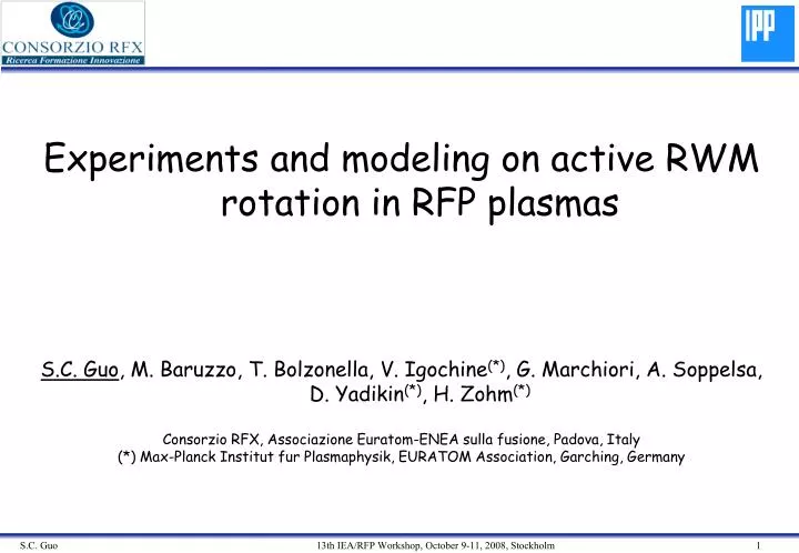
Experiments and modeling on active RWM rotation in RFP plasmas S.C. Guo , M. Baruzzo, T. Bolzonella, V. Igochine (*) , G. Marchiori, A. Soppelsa, D. Yadikin (*) , H. Zohm (*) Consorzio RFX, Associazione Euratom-ENEA sulla fusione, Padova, Italy

E N D
Experiments and modeling on active RWM rotation in RFP plasmas S.C. Guo, M. Baruzzo, T. Bolzonella, V. Igochine(*), G. Marchiori, A. Soppelsa, D. Yadikin(*), H. Zohm(*) Consorzio RFX, Associazione Euratom-ENEA sulla fusione, Padova, Italy (*) Max-Planck Institut fur Plasmaphysik, EURATOM Association, Garching, Germany
Outline • Introduction • RWM active rotation: experimental issues • RWM active rotation: first results • RWM active rotation modelling • Conclusions and future work
Introduction • Resistive Wall Modes (RWMs) are MHD instabilities common to many toroidal devices growing on timescales that depend on the typical penetration time of the surrounding passive boundary. • In both tokamaks and RFPs they can be viewed as serious performance limiting phenomena and for this reason studies on their very nature and, ultimately, on their control are very important. • In the tokamak case the stabilizing role played by plasma rotation is one of the most important open issues for present and future devices. • In the RFP case, numerical modelling suggested that only fluid rotation much faster than the ones normally observed in present RFP experiments can provide a similar role, but, also due to the lack of strong momentum input sources, experimental data are missing. • The new sets of experiments done on RFX-mod, and recently replicated on T2R, aim at providing inputs on both fundamental RWM physics and new possible control strategies.
RWM in RFPs: stabilization by rotation • In the RFP configuration plasma velocities needed for RWM stabilization are very high. The required flow velocities have to reach • kVo ≈ k//VA ≈ A. • Active feedback control is then, when implemented, the only stabilising mechanism for the RFP. S.C. Guo, J. P. Freidberg and R. Nachtrieb,”Stability of resistive wall modes in reversed field pinches with longitudinal flow and dissipative effects”, PoP (1999)
The RFX-mod active control system Actuators: 192 active coils 100% coverage of the mechanical structure external surface Each saddle coil is fed with its own power supply Inputs (real time): 192 independent saddle sensors (Br) + 192 pickup coils (Bt, for variable radius control) + 192 coil currents (for sideband correction) independent control on m=0,1,2 (partial), -23<n<24 Software control: Full PID digital controller. For the present experiments, optimized Clean Mode Control scheme was used (control gains relative to single Fourier modes)
Shot 17304 n=-3 ÷ -6 control offcontrol on RWM characterisation and control RWM experimental growth rates can be calculated with a high degree of reliability (e.g. (m=1, n=-5), F=-0.07 in left figure). Comparison with models can be done during the free growth and the active control phases. In right figure eigenfunction calculations done solving Newcomb equation (P. Zanca)
The idea (feedback rotation control) Plasma field Perfect control Total field=0 External field Plasma field Incomplete control Total field≠0 External field Plasma field Incomplete control with phase shift Total field≠0 External field
Proportional gain scan on n=-6; phase 0; F=-0.08 Effect of a real proportional gain scan on (1,-6) RWM: (a) mode amplitudes, (b) mode phases. Black full traces Gp=800 (full control), red squares Gp=200, cyan circles Gp=150 , blue diamonds Gp=100. Note that an extremely good reproducibility of the RWM growth rate can be obtained under controlled experimental conditions. Control from 130 ms
Phase scan at fixed (normal) Gp: 400 kA The induced rotation does not depend on the chosen direction. Effect of a complex proportional gain scan on 400 kA discharges: (a) mode amplitudes; (b) mode phases. Black full traces represent a reference shot where (1,-6) RWM is free to grow up to 0.13s and then is fully controlled. Red squares and blue diamonds traces show the effect of the application of a complex proportional gains: the rotation of a selected RWM can be induced in both opposite directions (feedback in action from 0.1s).
Phase scan at fixed (normal) Gp: 600 kA The induced rotation work in the same way at different plasma currents. 400 kA experiments 600 kA experiments
Induced rotation data analysis • Special care: sensor measurements (and Fourier components) during the control are relative to plasma+external fields! The question is then: what is actually rotating? • From total br measurements to plasma vs external fields • External br field at the measurement radius obtained from coil currents (including mutual inductances and machine structure). Model developed by G. Marchiori and A. Soppelsa • Plasma br field by subtraction • Time evolution of external and plasma harmonics (amplitude and phase)
Measurement components • Decomposition of the measured mode amplitude and phase into plasma and external field components: • full black line: total Br (1,-6) as measured by the sensor arrays; • blue diamonds: reconstructed plasma Br, • - red squares: reconstructed external Br applied by the active control system.
Modeling of induced rotation • Since the mode rational surface is outside the plasma, the usual torque theory is not appropriate to be applied • the following simple model is proposed: • Consider only one (m,n) mode in cylidrical geometry, ym,n satisfies Newcomb’s equation with extended boundary condition at rb (resistive walltb), ym,n (∞)=0 Inside plasma: (without feedback coils) C. G. Gimblett, Nuclear Fusion (1986)
Modeling of induced rotation In the vacuum: S(m,n) -the coefficient related to the structure of the feedback coils for the feedback circuit: (G=Gr+iGi) (including effects of resistive wall and complex gain) Dispersion relation for w:
Modeling of induced rotation Re(G)=const. ; Im(G)= Re(G)Tang(Df) Parameter in modelling: F=-0.05, q=1.47, eo=0.23 Without feedback, With real gain , if g ≤ 0 for With complex gain and
Conclusions • •It was demonstrated for the first time in RFPs that the internal non-resonant resistive wall mode can be detached from the resistive wall in a controlled way. • • The observed constant rotation of the mode depends on the phase shift between external perturbations and the mode. • It was experimentally confirmed that plasma rotation, plasma current and coupling to other modes have no impact on the rotation frequency of the RWM in the range explored. • Similar experiments started on T2R will allow better understanding of the boundary condition influences (both passive conductors and software control) • The proposed simple analytical model gives good description of the experimental results. This model can be further improved.