Download
1 / 20
210 likes | 380 Views
ENGIN 112 Intro to Electrical and Computer Engineering Lecture 7 More Logic Functions: NAND, NOR, XOR. Overview. More 2-input logic gates (NAND, NOR, XOR) Extensions to 3-input gates Converting between sum-of-products and NANDs SOP to NANDs NANDs to SOP

E N D
ENGIN 112Intro to Electrical and Computer EngineeringLecture 7More Logic Functions: NAND, NOR, XOR
Overview • More 2-input logic gates (NAND, NOR, XOR) • Extensions to 3-input gates • Converting between sum-of-products and NANDs • SOP to NANDs • NANDs to SOP • Converting between sum-of-products and NORs • SOP to NORs • NORs to SOP • Positive and negative logic • We use primarily positive logic in this course.
x 0 0 1 1 y 0 1 0 1 G 0 0 0 1 Logic functions of N variables • Each truth table represents one possible function (e.g. AND, OR) • If there are N inputs, there are 22N • For example, is N is 2 then there are 16 possible truth tables. • So far, we have defined 2 of these functions • 14 more are possible. • Why consider new functions? • Cheaper hardware, more flexibility.
The NAND Gate A Y • This is a NAND gate. It is a combination of an AND gate followed by an inverter. Its truth table shows this… • NAND gates have several interesting properties… • NAND(a,a)=(aa)’ = a’ = NOT(a) • NAND’(a,b)=(ab)’’ = ab = AND(a,b) • NAND(a’,b’)=(a’b’)’ = a+b = OR(a,b) B
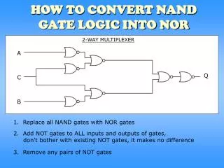
The NAND Gate • These three properties show that a NAND gate with both of its inputs driven by the same signal is equivalent to a NOT gate • A NAND gate whose output is complemented is equivalent to an AND gate, and a NAND gate with complemented inputs acts as an OR gate. • Therefore, we can use a NAND gate to implement all three of the elementary operators (AND,OR,NOT). • Therefore, ANY switching function can be constructed using only NAND gates. Such a gate is said to be primitive or functionally complete.
NAND Gates into Other Gates A Y A Y B A Y B (what are these circuits?) NOT Gate AND Gate OR Gate
The NOR Gate • This is a NOR gate. It is a combination of an OR gate followed by an inverter. It’s truth table shows this… • NOR gates also have several interesting properties… • NOR(a,a)=(a+a)’ = a’ = NOT(a) • NOR’(a,b)=(a+b)’’ = a+b = OR(a,b) • NOR(a’,b’)=(a’+b’)’ = ab = AND(a,b) A Y B
Functionally Complete Gates • Just like the NAND gate, the NOR gate is functionally complete…any logic function can be implemented using just NOR gates. • Both NAND and NOR gates are very valuable as any design can be realized using either one. • It is easier to build an IC chip using all NAND or NOR gates than to combine AND,OR, and NOT gates. • NAND/NOR gates are typically faster at switching and cheaper to produce.
NOR Gates into Other Gates A Y A Y B A Y B (what are these circuits?) NOT Gate OR Gate AND Gate
The XOR Gate (Exclusive-OR) • This is a XOR gate. • XOR gates assert their output when exactly one of the inputs is asserted, hence the name. • The switching algebra symbol for this operation is , i.e. 1 1 = 0 and 1 0 = 1. A Y B
The XNOR Gate • This is a XNOR gate. • This functions as an exclusive-NOR gate, or simply the complement of the XOR gate. • The switching algebra symbol for this operation is , i.e. 1 1 = 1 and 1 0 = 0. A Y B
NOR Gate Equivalence • NOR Symbol, Equivalent Circuit, Truth Table
DeMorgan’s Theorem • A key theorem in simplifying Boolean algebra expression is DeMorgan’s Theorem. It states: (a + b)’ = a’b’ (ab)’ = a’ + b’ • Complement the expression a(b + z(x + a’)) and simplify. (a(b+z(x + a’)))’ = a’ + (b + z(x + a’))’ = a’ + b’(z(x + a’))’ = a’ + b’(z’ + (x + a’)’) = a’ + b’(z’ + x’a’’) = a’ + b’(z’ + x’a)
Example • Determine the output expression for the below circuit and simplify it using DeMorgan’s Theorem
Universality of NOR gate • Equivalent representations of the AND, OR, and NOT gates
Interpretation of the two NAND gate symbols • Determine the output expression for circuit via DeMorgan’s Theorem
Interpretation of the two OR gate symbols • Determine the output expression for circuit via DeMorgan’s Theorem
Summary • Basic logic functions can be made from NAND, and NOR functions • The behavior of digital circuits can be represented with waveforms, truth tables, or symbols • Primitive gates can be combined to form larger circuits • Boolean algebra defines how binary variables with NAND, NOR can be combined • DeMorgan’s rules are important. • Allow conversion to NAND/NOR representations