Download
1 / 46
460 likes | 594 Views
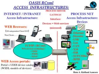
(c) 2013 R. Newman University of Florida. CEBus. What is CEBus. Consumer Electronics Bus (See-bus) Electronic Industries Association (EIA) Standard for Physical interface for devices in the home to exchange information (TPBus, CXBus, PLBus, …) Common language for them to “talk” (CAL)

E N D
(c) 2013 R. Newman University of Florida CEBus
What is CEBus • Consumer Electronics Bus (See-bus) • Electronic Industries Association (EIA) Standard for • Physical interface for devices in the home to exchange information (TPBus, CXBus, PLBus, …) • Common language for them to “talk” (CAL) • Three aims: • Universal, low-cost, generic communication method for in-home devices • Reliable distribution of access services in the home • Reliable distribution of wide-band services within the home (e.g., DVR to TV, home theater, etc.) • Multiple media: TP, Coax (2 cables), PL, RF, IR
CEBus History • Pre-1984 – X10, GE’s Homenet existing PLC methods • 1984 – EIA starts standards process IS60 • 1985 – field tests for PLC • 1986 – GE provides Homenet as a basis for CEBus (GE used X10 for their HomeMinder products), PLC 120 KHz 1Kbps ASK, CEBus named • 1989 – demos at winter CES, ASK PLBus ballot • 1991 – Intellon’s 10Kpbs spread spectrum PHY replaces ASK due to X10 incompatibility (“all lights on”) • 1992 - FCC part 15 rule amended for PLC, EIA releases Interim Standard (IS60) • 1994 – Standard revised • 1995 – IS 60 becomes ANSI/EIA standard EIA 600
CEBus Standards • Physical Layer/media IS-60.03/EIA-600.3x • 9 Parts: PL (1), TP (2), CX (3), IR (4) RF (5), FO (6), TP/CX/IR symbols (7), PL/RF symbols (8), ‘Node 0’ PHY NW support fcns (9) • Node Comm’s Protocol IS-60.04/EIA-600.4x • Part 1 Data Link, Part 2 MAC, Part 3 LL, Part 4 Network Layer Description, Part 5 Network Layer, Part 6 Application Layer • Router Comm Protocol IS-60.05/EIA-600.5x • 4 parts describing router function • Brouter Comm Protocol IS-60.06/EIA-600.6x • 4 parts describing brouter (wired/non-wired) function • Supplemental Data IS-60.07/EIA-600.7x • For future – not used • Common Application Language (CAL) IS60.08/EIA-600.8x • Part 1 CAL, Part 2 CAL Contexts (universal, data channel, tune, user interface) • Separate docs for context data structures • Lighting, audio/video, security, HVAC
CEBus Design Constraints • Unskilled installer/user • Incremental installation • No preconceived network • Primarily residential network • Fast enough for existing residential tasks • 100 ms. max delay for light switch effect • Troubleshooting will be difficult • Security optional • Cable boxes, electric meters
CEBus Physical Layer/media • PL (part 1) – 110/220 V. power lines • Use existing wiring, any AC powered device • TP (part 2) – four twisted pairs • Low DC voltage devices – thermostats, sensors • In place of or supplemental to phone wiring • CEBus distributes 18 V. to devices on TP0 • CX (part 3) – two coax cables • For ‘cabled’ devices like TV, VCR, DVR, etc. • One for in-home sources • One for external (access) sources • IR (part 4) • Line of sight (in-room) wireless – similar to remote controls • RF (part 5) • 915 MHz center, for “throughout home” wireless • FO (part 6) – fiber optics part not completed (interest?)
CEBus Node Communications Protocol (Volume 4) • Follows ISO OSI reference architecture • Data Link Layer with 2 sub-layers • MAC – packet delivery, error handling, addressing, packet time, buffering • LLC – mostly interface to Network • Network Layer • Reliable message delivery, medium selection, routing, duplicate rejection (wireless), flow control, fragmentation/reassembly • Application Layer • Message generation, reception, ACK, execution, CAL
CEBus Network Control • Peer-to-peer distributed control • Any node can control any other node • Nodes can be added at any time without registration with central controller • Cluster control • Not required, but allowed • User interface node (say, TV) can contact cluster control node that knows how to carry out coordinated behavior in product cluster (e.g., thermostat to compressor, blower, …)
CEBus Media Topology RF RF Brouter CX Distribution Device Cable Provider CX CX NUI Router Data Bridge TP TP NUI TP Distribution Device Telco IR Router Data Bridge IR Brouter PL NUI Utility PL Node 0 Node 0 meter
CEBus Routers and Brouters • Routers • Connect control channel of two wired media • Forwarding table with addresses • Maintain tree topology • Periodic HELLO messages only to routers • Detect duplicate HELLO then turn off routing • Brouters – Bridging routers • Connect control channel of wired and wireless • Duplicate packets from wireless side • Handle duplicate data packets differently • Data Bridges • Reserve data channel using control channel • Retransmit data in destination medium
CEBus Channels • Control Channel • Required • CEBus device message communications • CAL messages • 10 Kbps • Data Channel (CX, TP) • Optional • Reserved frequency space • Device specific – not interpreted • Voice/Music/Video/Data – digital/analog
CEBus TP Data Channels • Twisted Pair (TP) – 0-1 MHz • 4 twisted pairs • 128 channels (32 per each pair) • 0-3 on TP-0 are for control channel, rest for data • 32 KHz spacing • 10 KHz in-channel • Sloping channel amplitude roll-off to -40dB • 500 mV to 150 mV p-p depending on channel • Adjacent channels can be concatenated for larger bandwidth needs • Maximum power on concatenated channels is minimum of any channel in the concatenated group • Reserved through CAL naming “bands” that include concatenated channels in powers of 2
CEBus CX Data Channels • Two RG-6 coaxial cables (75 Ohm) • Internal • Control channel • Data channels 1-64 • External • “Off air” VHF/UHF/FM and cable TV • Optional in-home generated video • Frequency Bands • 50-150 MHz • 64 bands of 1.5 MHz (-9 dBmV center-24 edges) • 4 adjacent bands (6 MHz) used for SDTV (+6dBmV allowed)
CEBus Packet Structure DL svcs To addr From addr Network Services Application Services Pre- amble CAL message FCS • Payload (CAL message/reply) • 4-10 bytes (25-50% of packet) • Addresses • House/device – acquired when installed • Data Link Services • Priority, ACK requested • Network Services • For routing • Application Services • Reply requested/authentication/encryption
CEBus Physical Layer (PHY) • Four functions • Symbol timing • Detect valid symbols on reception • Add/check 16-bit CRC (RF & PL) • Inform DLL of medium state for access control • Two sublayers • Symbol Encoding Sublayer • Medium Dependent Sublayer
CEBus PHY • Symbol Encoding Sublayer • Symbol encoding/decoding • Symbol timing/bit error detection • CRC generation/checking (PL, RF) • Channel state detection • Medium Dependent Sublayer • SUPERIOR/INFERIOR state generation/detection • Medium interface
CEBus Symbols • Two physical medium states • Superior: dominates inferior • Inferior: also idle state • Always alternate, starting with superior • Quaternary symbols – timing encoded • 1: 100 usec (1 Unit Symbol Time) • 0: 200 usec (2 UST) • EOF: 300 usec (3 UST) • EOP: 400 usec (4 UST) • Timing +/- 50 usec • If <50 or >450 usec => bit error
CEBus Symbols • Data Rate • Same for all media • 10,000 1-bits/sec • Actual rate around 8,500 bps • Signaling technology • Lowest cost, highest reliability per medium • 100-400 kHz spread spectrum PL • 10 kHz 250 mV carrier TP • 4.5-5.5 MHz carrier CX • 100 kHz 850-1000 nm IR • 915 center MHz spread spectrum RF
CEBus PL Symbols • Not traditional DSSS or FHSS • Each “Chirp” sweeps 200 kHz-400kHz, jumps to 100 kHz then sweeps to 200 kHz • Rounded waveform synthesized from 360 digitized values given in the standard • Reduces out-of-band amplitude • Meets FCC emission requirements • < 100 kHz under 5 mV • Avoids interfering with LORAN, etc. • > 400 kHz under 1 mV • Avoids interfering with cheap AM radios
CEBus PL Spread Spectrum Signal Element Powerline spread spectrum SUPERIOR 01 wave form – “chirp”
CEBus PL Symbols • 25 cyclic sweeps per UST (100 usec) • 0, EOF, EOP formed by repeating form • Superior state is PL SUPERIOR 01 form • SUPERIOR 02 form = inverted SUPERIOR 01 • Inferior state varies • Preamble and idle Inferior = no signal • Needed by DLL to detect collisions • Information in packet Inferior = SUPERIOR 02 • Needed to keep carrier present, maintain sync • Greatly enhances reliability (why?)
CEBus PL Sigelts SUPERIOR 01 SUPERIOR 02 Powerline spread spectrum SUPERIOR 01 and SUPERIOR 02 wave forms
CEBus PL Symbols 1 0
CEBus RF Symbols • Digitally synthesized 915 MHz carrier • 4.3 to 6.2 MHz direct sequence spreading fcn • Double sideband • Carrier always on during transmission • Forward and reverse spreading codes, F and R • F is 3 1’s, 3 0’s … 2 1’, 2 0’s, R is reverse of this • Each used in 7 substates per UST, 360 chips per substate • Two SUPERIOR states • SUPERIOR 01 = FFFRRFR • SUPERIOR 02 = RRRFFRF • Alternate SUPERIOR 01 and 02 • 0, EOF, EOP formed by repeating form • Inferior state varies • Preamble and idle Inferior = no signal • Needed by DLL to detect collisions • Information in packet Inferior = SUPERIOR 02 • Needed to keep carrier present, maintain sync • Greatly enhances reliability (why?)
CEBus Other Symbols • TP – 10 KHz baseband • Bipolar SUPERIOR state • +/- 150-600 mV. alternate every 100 usec • no DC bias • CX – 5.5 MHz ASK • 100 mV. p-p SUPERIOR • IR – 100 KHz ASK • 850-1000 nm. IR source • All of the above • No signal INFERIOR state • Alternate SUPERIOR and INFERIOR • Symbol determined by state duration
CEBus Packet Format • Preamble • Detect frames, detect & resolve collisions • FCS • 8-bit checksum appended by DLL (CX, TP, IR) • Checksum is sum (excl. preamble) with carries dropped • 16-bit CRC appended by PHY (PL, RF) • Packets 50-350 bits long
CEBus Datalink Layer (DLL) • Builds and parses complete DL PDU • Generate preamble • Leading zero suppression (compression) • FCS generation (TP, CX, IR) • Error detection • Address recognition • Duplicate rejection • Executes channel access protocol • Provides immediate acknowledged packet delivery service
CEBus DL PDU • Preamble • 8-bit random value derived for each DLPDU • Control • SN = 1 bit sequence number • SC = Service Class (0 basic, 1 extended) • X = not used • 3 Priority Levels (00=High, 01=Std, 10=Deferred) • Service (Acknowledgement handling) • Addresses • 32-bit hierarchical addresses
CEBus Addresses • Hierarchical • 16-bit System (home) address • 16-bit Node address • Node address • Individual – unique to node • Group – multicast • Broadcast - 0000 • FROM address may be omitted at times • If no reply is needed – specifically when… • AL implicit_invoke + not NL Extended Service + not DL “addressed” service
EOF, EOP, LZS • EOF = End of Field • Delimits all fields except NPDU • Allows variable length fields, zero suppression • EOP = End of Packet • Delimits end of DLPDU, after FCS • LZS = Leading Zero Suppression • Leading zeros omitted on all fields except preamble and NPDU • Simple compression method • Biggest gain in address fields
CEBus Channel Access • CSMA/CDCR • Carrier Sense Multiple Access • “listen before talk” • 0-3 UST random wait before transmission • Collision Detection and Collision Resolution • Nodes can detect collisions when they occur • Collisions are resolved in favor of one node • Immediate retransmissions as necessary • Priority • Affects access timing • Round robin queuing within priorities
CEBus Collision Resolution • If detect another transmission before starting transmission, defer • 25 usec. to detect other Tx, so can collide • Sender in INFERIOR state can detect another sending in SUPERIOR state • If detect another transmission (SUPERIOR state while sending INFERIOR), then defer • Usually will happen in (random) preamble
CEBus Priority • Priority determined by application • 3 levels • 00=High (user interaction) • 01=Standard (default) • 10=Deferred (no time sensitivity) • Determines how soon can you contend after required 10 UST quiet period after last packet • High = 11 UST after previous packet • Standard = 15 UST after previous packet • Deferred = 19 UST after previous packet
CEBus Fairness • Prevent starvation of lower priority packets • A priority can be in one of two states • Queued • Transmit at earliest time available for priority • Unqueued • Wait 4 additional UST for priority level • Queued Priority State Changes • If DLL gains access without contention and transmits a packet, enter unqueued state for that priority • If contention stops transmission, enter queued state
CEBus Access • Acknowledgement must be sent within 200 usec. • Measured at receiver • If no ACK received by 600 usec., sender may resend • Measured at sender • ACK should arrive at sender between 300 and 600 usec. • Earliest start for other packets is 1000 usec (10 UST) • Each priority levels has two windows of 4 UST each • One window for queued, one for unqueued priority state
CEBus ACK Services • FAIL (100) • Response to ack service pkt • SN=SC=Priority=Service=0, no SA or DA • Indicates packet received correctly, but… • Information field contains reason for failure • 01 = Remote busy (receiver can’t process packet now) • 80 = Remote reject (receiver can’t process packets) • Sender must report failure to Network Layer • Remote Busy • Sender DLL queues pkt for retransmission • Busy Queue state adds a delay of 12 UST to existing packet access delay, in effect as long as Busy received • If re-Tx gets no ACK, re-Tx delay = 0
CEBus UnACKed Services • Unacknowledged (010) – no ACK • Broadcast, multicast, or unicast • SN set to 0, SC=0, SA optional • Addressed unacknowledged (111) • Intended to make multicast/broadcast more reliable • Packet may be repeated (using access at priority level) until 750 msec. from start of first send to end of last one (usu. 2-3 times) • Source address required, SC=0 • SN used – with SA, reject duplicates • Receiver keeps association info for 938 msec. or until new SN received from same SA • Sender prohibited from using same SN for same receiver(s) for 1125 msec.
CEBus ACKed Services • Acknowledged (001) – ACK • Broadcast, multicast, or unicast • SN set to 0, SC=0, SA optional • Receiver must send ACK within 200 usec. • Sender gets one retry at 600 usec. • Addressed acknowledged (101) • Source address required, SN used, SC=0 • Receiver may retry once at 600 usec. • If additional retries needed, compete for access for up to 750 msec. after first transmission starts • Association storage timing like addressed unacked • Helps solve near-far ACK problem
CEBus ACKs • Acknowledgement (000) • Response to ack service pkt • SN=SC=Priority=Service=0, no SA or DA • Leading zero suppression leaves short pkt: Preamble-EOF-EOF-FCS-EOP • Addressed acknowledgement (110) • Response to addressed ack service pkt • SC=Priority=0, SN used (same as pkt ack’ed) • SA used, Info field present 00 = Success 01 = Remote busy (retry later) 80 = Remote reject 100-FFFF = Other (reserved)
CEBus Network Layer (NL) • Build/parse NPDU • ID pkt generation/detection • Optional segmented service • Optional flow control • IR/RF duplicate packet rejection
CEBus NPDU Header Routing 11: Flood 10: Directory 01: ID Packet 00: Request ID FP, Ext First pkt, Extended Services byte present AM Allowed Media field present B1, B2 Brouter addresses present
NL Extended Service Byte • Extended Service Type • 1100: Seg_service – segmented service • 0110: Num_pkt – for RF, IR duplicate rejection • 1011: Pos_ack – used with flow control • 1010: Neg_ack – used with flow control • 1001: No_serv_support – request for segt svc denied • 0100: Seg_serv_busy – temporarily unable to Rx segt • 0010: Error_msg_length – segmented pkt too big • Message Number Toggle • bit toggles with each APDU, stays same for all segts of APDU • Flow Control – if 1, flow control requested • Flow Control Window Size – used with flow control • Window size is 2 plus binary value of window bits
NL Packet Numbers • Packet number byte(s) follow Ext Svc Byte • Numbered Packet Ext Svc • for RF, IR duplicate rejection • Pkt number byte holds value to allow receiver to detect pkt forwarded by multiple wireless brouters when brouter addresses are not used • 8-bit value decremented with each pkt sent • Number cannot be reused for 5 sec. • Segmented Service Ext Svc • Packet number indicated remaining segments in segmented APDU (last one is 0) • First segement indicated by FP=1 in NPDU header • More than 254 segments => multiple packet number bytes, with 255 value in initial bytes, each indicating 254 sgts plus whatever follows
NL Segmented Service • Large APDU broken into segments (say 3) • First segment • NPDU Service Byte: FP=1, Ext=1 • ES Byte: ES Type = 12 (Segt svc), M#=1 (say) • Packet Number = 2 • Second segment • NPDU Service Byte: FP=0, Ext=1 • ES Byte: ES Type = 12 (Segt svc), M#=1 (say) • Packet Number = 1 • Second segment • NPDU Service Byte: FP=0, Ext=1 • ES Byte: ES Type = 12 (Segt svc), M#=1 (say) • Packet Number = 0
NL Flow Control • May be used with unicast segmented service • Requires receiver to acknowledge a group of packets • Size of group indicated by window field • Group size = window value + 2 • After sending last pkt in window, sender NL waits for ACK or NAK • NAK or timeout => resend since last good pkt • ACK packet number indicates last packet number in correctly received group • NAK sent immediately if loss or error detected • Packet number indicates last good packet received
NL Brouter Addresses • Brouter address bits B1, B2 • If = 1, then brouter address present • Used to eliminate duplicate packets • Single brouter address used when multiple brouters may receive wireless packet, so only one will forward packet • Second brouter address used when destination is on wireless medium, selects the brouter designated to forward over last hop