Download
1 / 119
1.21k likes | 1.45k Views
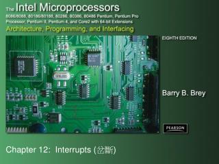
Chapter 12: Interrupts ( 岔斷 ). Introduction. In this chapter, the coverage of basic I/O and programmable peripheral interfaces is expanded by examining a technique called interrupt-processed I/O .

E N D
Introduction • In this chapter, the coverage of basic I/O and programmable peripheral interfaces is expanded by examining a technique called interrupt-processed I/O. • An interrupt is a hardware-initiated procedure that interrupts whatever program is currently executing. • This chapter provides examples and a detailed explanation of the interrupt structure of the entire Intel family of microprocessors.
Chapter Objectives Upon completion of this chapter, you will be able to: • Explain the interrupt structure of the Intel family of microprocessors. • Explain the operation of software interrupt instructionsINT, INTO, INT 3, and BOUND. • Explain how the interrupt enable flag bit (IF) modifies the interrupt structure. • Describe the function of the trap interrupt flag bit (TF) and the operation of trap-generated tracing.
Chapter Objectives (cont.) Upon completion of this chapter, you will be able to: • Develop interrupt-service procedures that control lower-speed, external peripheral devices. • Expand the interrupt structure of the microprocessor by using the 8259A programmable interrupt controller andother techniques. • Explain the purpose and operation of a real-time clock.
12–1 BASIC INTERRUPT PROCESSING • This section discusses the function of an interrupt in a microprocessor-based system. • Structure and features of interrupts availableto Intel microprocessors.
The Purpose of Interrupts • Interrupts are useful when interfacing I/O devices at relatively low data transfer rates, such as keyboard inputs, as discussed in Chapter 11. • Interrupt processing allows the processor to execute other software while the keyboard operator is thinking about what to type next. • When a key is pressed, the keyboard encoder debounces the switch and puts out one pulse that interrupts the microprocessor.
Figure 12–1 A time line that indicates interrupt usage in a typical system. • a time line shows typing on a keyboard,a printer removing data from memory, and a program executing • the keyboard interrupt service procedure, called by the keyboard interrupt, and the printer interrupt service procedure each take little time to execute
Interrupts • Intel processors include two hardware pins (INTR and NMI) that request interrupts… • And one hardware pin (INTA) to acknowledge the interrupt requested through INTR. • The processor also has software interrupts INT, INTO, INT 3, and BOUND. • Flag bits IF (interrupt flag) and TF (trap flag), are also used with the interrupt structure and special return instruction IRET • IRETD in the 80386, 80486, or Pentium
Interrupt Vectors • Interrupt vectors and the vector table are crucial to an understanding of hardwareand software interrupts. • The interrupt vector table is located inthe first 1024 bytes of memory at addresses 000000H–0003FFH. • contains 256 different four-byte interrupt vectors • An interrupt vector contains the address (segment and offset) of the interrupt service procedure.
Figure 12–2 (a) The interrupt vector table for the microprocessor and (b) the contents of an interrupt vector. • the first five interrupt vectors are identicalin all Intel processors • Intel reserves the first 32 interrupt vectors • the last 224 vectors are user-available • each is four bytes long in real mode and contains the starting address of the interrupt service procedure. • the first two bytes contain the offset address • the last two contain the segment address
Intel Dedicated Interrupts • Type 0The divide error whenever the result from a division overflows or an attempt is made to divide by zero. • Type 1Single-step or trap occurs after execution of each instruction if the trap (TF) flag bit is set. • upon accepting this interrupt, TF bit is clearedso the interrupt service procedure executes atfull speed
Type 2The non-maskable interrupt occurs when a logic 1 is placed on the NMI input pin to the microprocessor. • non-maskable—it cannot be disabled • Type 3A special one-byte instruction (INT 3) that uses this vector to access its interrupt-service procedure. • often used to store a breakpoint in a programfor debugging
Type 4Overflow is a special vector used with the INTO instruction. The INTO instruction interrupts the program if an overflowcondition exists. • as reflected by the overflow flag (OF)
Type 5The BOUND instruction compares a register with boundaries stored in the memory. If the contents of the register are greater than or equal to the first word in memory and less than or equal to the second word, no interrupt occurs because the contents of the register are within bounds. • if the contents of the register are out of bounds,a type 5 interrupt ensues
Type 6An invalid opcode interrupt occurs whenan undefined opcode is encountered in a program. • Type 7The coprocessor not available interrupt occurs when a coprocessor is not found, as dictated by the machine status word (MSWor CR0) coprocessor control bits. • if an ESC or WAIT instruction executes and no coprocessor is found, a type 7 exception or interrupt occurs
Type 8A double fault interrupt is activated whentwo separate interrupts occur during thesame instruction. • Type 9The coprocessor segment overrun occursif the ESC instruction (coprocessor opcode) memory operand extends beyond offset address FFFFH in real mode.
Type 10An invalid task state segment interrupt occurs in the protected mode if the TSS is invalid because the segment limit field is not 002BH or higher. • usually because the TSS is not initialized • Type 11The segment not present interrupt occurs when the protected mode P bit (P = 0) in a descriptor indicates that the segment is not present or not valid.
Type 12A stack segment overrun occurs if thestack segment is not present (P = 0) in the protected mode or if the limit of the stack segment is exceeded.
Type 13The general protection fault occurs formost protection violations in 80286–Core2in protected mode system. These errors occur in Windows as general protection faults.A list of these protection violations follows.
(cont.) • Type 13protection violations • (a) Descriptor table limit exceeded • (b) Privilege rules violated • (c) Invalid descriptor segment type loaded • (d) Write to code segment that is protected • (e) Read from execute-only code segment • (f) Write to read-only data segment • (g) Segment limit exceeded
(h) CPL = IOPL when executing CLTS (Page 814, Clear task switched flag), HLT (Halt), LGDT (Load global descriptor table, pp.834), LIDT (Load interrupt descriptor table), LLDT (Load local descriptor), LMSW (Load machine status word), or LTR (Load task register) • (i) CPL > IOPL when executing CLI (Clear interrupt flag), IN (Input data from port), INS (Input string form port), LOCK (Lock the bus), OUT (Output data to port), OUTS (Output string to port), and STI (Set interrupt flag) CPL (Current privilege level); IOPL (Input/output privilege level)
Type 14Page fault interrupts occur for any pagefault memory or code access in 80386, 80486, and Pentium–Core2 processors. • Type 16Coprocessor error takes effect when a coprocessor error (ERROR = 0) occursfor ESCape or WAIT instructions for 80386, 80486, and Pentium–Core2 only.
Type 17Alignment checks indicate word and doubleword data are addressed at an odd memory location (or incorrect location, in the case of a doubleword). • interrupt is active in 80486 and Pentium–Core2 • Type 18A machine check activates a system memory management mode interrupt in Pentium–Core2.
Interrupt Instructions: BOUND, INTO, INT, INT 3, and IRET • Five software interrupt instructions are available to the microprocessor: • INT and INT 3 are very similar. • BOUND and INTO are conditional. • IRET is a special interrupt return instruction.
BOUND : Check array against boundary • INTO: Interrupt on overflow • INT: Interrupt • INT 3: Interrupt 3 • IRET: Return from interrupt
BOUND has two operands, and compares a register with two words of memory data. • INTO checks or tests the overflow flag (O). • If O = 1, INTO calls the procedure whose address is stored in interrupt vector type 4 • If O = 0, INTO performs no operation and thenext sequential program instruction executes • The INT n instruction calls the interrupt service procedure at the addressrepresented in vector number n.
INT 3 instruction is often used as a breakpoint-interrupt because it is easy to insert a one-byte instruction into a program. • breakpoints are often used to debug software • The IRET instruction is a special return instruction used to return for both software and hardware interrupts. • much like a far RET, it retrieves the return address from the stack
Operation of a Real Mode Interrupt • When the processor completes executing the current instruction, it determines whether an interrupt is active by checking: • (1) instruction executions • (2) single-step • (3) NMI • (4) coprocessor segment overrun • (5) INTR • (6) INT instructions in the order presented
If one or more are present: • 1. Flag register contents are pushed on the stack • 2. Interrupt (IF) & trap (TF) flags clear, disabling the INTR pin and trap or single-step feature • 3. Contents of the code segment register (CS) are pushed onto the stack • 4. Contents of the instruction pointer (IP) are pushed onto the stack • 5. Interrupt vector contents are fetched andplaced into IP and CS so the next instruction executes at the interrupt service procedure addressed by the vector
Operation of a Protected Mode Interrupt • In protected mode, interrupts have the same assignments as real mode. • the interrupt vector table is different • In place of interrupt vectors, protected mode uses a set of 256 interrupt descriptors stored in an interrupt descriptor table (IDT). • the table is 256 8 (2K) bytes long • each descriptor contains eight bytes
The interrupt descriptor table is located atany memory location in the system by the interrupt descriptor table address register (IDTR). • Each IDT entry contains the address of the interrupt service procedure • in the form of a segment selector and a 32-bit offset address • also contains the P bit (present) and DPL bitsto describe the privilege level of the interrupt • Fig 12–3 shows interrupt descriptor contents.
Interrupt Flag Bits • The interrupt flag (IF) and the trap flag (TF) are both cleared after the contents of the flag register are stacked during an interrupt. • the contents of the flag register and the location of IF and TF are shown here • when IF is set, it allows the INTR pin to causean interrupt • when IF is cleared, it prevents the INTR pinfrom causing an interrupt
Figure 12–4 The flag register. (Courtesy of Intel Corporation.) • when TF = 1, it causes a trap interrupt (type 1)to occur after each instruction executes • Trap is often called a single-step • when TF = 0, normal program execution occurs • the interrupt flag is set and cleared by the STIand CLI instructions, respectively • the contents of the flag register and the locationof IF and TF are shown here
Trace Procedure • Assuming TRON is accessed by an INT 40H instruction and TROFF is by an INT 41H instruction, Example 12–3 traces through a program immediately following the INT 40H instruction. • The interrupt service procedure illustrated in Example 12–3 responds to interrupt type 1or a trap interrupt.
Storing an Interrupt Vector in the Vector Table • To install an interrupt vector—sometimes called a hook—the assembler must address absolute memory. • Example 12–4 shows how a new vector is added to the interrupt vector table using the assembler and a DOS function call. • Function AX = 3100H for INT 21H, installsthe NEW40 procedure until the PC is shut off.
12–2 HARDWARE INTERRUPTS • The two processor hardware interrupt inputs: • non-maskable interrupt (NMI) • interrupt request (INTR) • When NMI input is activated, a type 2 interrupt occurs • because NMI is internally decoded • The INTR input must be externally decodedto select a vector.
Any interrupt vector can be chosen for the INTR pin, but we usually use an interrupttype number between 20H and FFH. • Intel has reserved interrupts 00H - 1FH for internal and future expansion. • INTA is also an interrupt pin on the processor. • it is an output used in response to INTR inputto apply a vector type number to the data bus connections D7–D0 • Figure 12–5 shows the three user interrupt connections on the microprocessor.
Figure 12–5 The interrupt pins on all versions of the Intel microprocessor.
The non-maskable interrupt (NMI) is an edge-triggered input that requests an interrupt on the positive edge (0-to-1 transition). • after a positive edge, the NMI pin must remain logic 1 until recognized by the microprocessor • before the positive edge is recognized, NMI pin must be logic 0 for at least two clocking periods • The NMI input is often used for parity errors and other major faults, such as power failures. • power failures are easily detected by monitoring the AC power line and causing an NMI interrupt whenever AC power drops out
Figure 12–6 shows a power failure detection circuit that provides logic 1 to the NMI input whenever AC power is interrupted. • In this circuit, an optical isolator provides isolation from the AC power line. • The interrupt service procedure stores the contents of all internal registers and other data into a battery-backed-up memory. • This assumes the PC power supply has a large enough filter capacitor to provide energy for at least 75 ms after the AC power ceases.
Figure 12–7 shows a circuit that supplies power to a memory after the DC power fails. • diodes are used to switch supply voltages from the DC power supply to the battery • When DC power fails, the battery provides a reduced voltage to the VCC connection on the memory device. • Most memory devices will retain data withVCC voltages as low as 1.5 V, so the battery voltage does not need to be +5.0 V.
Figure 12–7 A battery-backed-up memory system using a NiCad, lithium, or gel cell.
INTR and INTA • The interrupt request input (INTR) is level-sensitive, which means that it must be held at a logic 1 level until it is recognized. • INTR is set by an external event and cleared inside the interrupt service procedure • INTR is automatically disabled once accepted. • re-enabled by IRET at the end of the interrupt service procedure • 80386–Core2 use IRETD in protected mode. • in 64-bit protected mode, IRETQ is used
The processor responds to INTR by pulsing INTA output in anticipation of receiving an interrupt vector type number on data bus connections D7–D0. • Fig 12–8 shows the timing diagram for the INTR and pins of the microprocessor. • Two INTA pulses generated by the system insert the vector type number on the data bus. • Fig12–9 shows a circuit to appy interrupt vector type number FFH to the data bus in response to an INTR.
Figure 12–8 The timing of the INTR input and INTA output. *This portion of the data bus is ignored and usually contains the vector number.
Figure 12–9 A simple method for generating interrupt vector type number FFH in response to INTR.
Using a Three-State Buffer for INTA • Fig 12–10 shows how interrupt vector type number 80H is applied to the data bus (D0–D7) in response to an INTR. • In response to INTR, the processor outputs the INTA to enable a 74ALS244 three-state octal buffer. • The octal buffer applies the interrupt vector type number to the data bus in response. • The vector type number is easily changed with DIP switches shown in this illustration.
Figure 12–10 A circuit that applies any interrupt vector type number in response toINTA. Here the circuit is applying type number 80H.