Download
1 / 18
190 likes | 343 Views
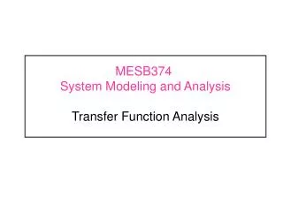
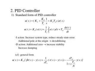
MESB374 System Modeling and Analysis PID Controller Design. PID Controller. Structure of Controller Effects of Proportional, Integral and Derivative Actions Design of PID Controllers. Disturbance D (s). Reference Input R ( s ). Control Input U ( s ). +. Output Y (s). Error E ( s ).

E N D
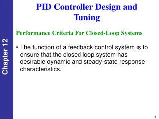
PID Controller • Structure of Controller • Effects of Proportional, Integral and Derivative Actions • Design of PID Controllers
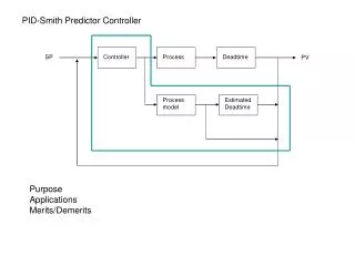
Disturbance D(s) Reference Input R(s) Control Input U(s) + Output Y(s) Error E(s) + + GC (s) Gf (s) - Plant H(s) G(s) PID Controller Proportional plus Integral plus Derivative (PID) Control In time domain current information passed information (prediction of) future information In s-domain
Effect of P-I-D Actions • Derivative Action (KCD s): Provides added damping to the closed-loop system; reduces overshoot and oscillation in step response; tends to slow down the closed-loop system response. Dominant during initial transient, due to the effect of differentiation. • Integral Action (KCI /s): Eliminates steady-state error to step inputs; tends to destabilize the closed-loop system; has averaging effect. Dominant during steady-state by producing an accumulation of steady-state error to increase control effort. • Proportional Action (KCP): Introduces immediate action due to error; improves system response time. Has similar control authority for both transient and steady-state.
Disturbance D(s) Output Y(s) + Reference input R(s) + Effect of PID Actions • Ex: For a given process • Unit step disturbance response • Unit step reference response
Disturbance D(s) Reference Input R(s) Control Input U(s) + Output Y(s) Error E(s) + + GC (s) - Plant Effect of P Action • Objective: Design a system that has zero steady state error for step inputs with %OS<10% and Ts (2%)<6 [sec] (A.) Let’s try Proportional control: GC(s)=KCP CLTF:
Img. Axis 15 10 5 Real Axis 0 -25 -20 -15 -10 -5 0 5 -5 Effect of P Action Stability: 0<K CP <14.1 (A.1) Design P Control using Root Locus: CLCE: -7.5 -0.667 -10 -15 Not valid
Effect of P Action (A.2) Check for Steady State Error: Unit Step Reference Response Do NOT forget Stability: 0<K CP <14.1 Larger gain results in smaller steady-state error. Unit Step Disturbance Response Larger gain results in stronger attenuation of disturbance. Think about the change of overshoot when gain increases
Disturbance D(s) Reference Input R(s) Control Input U(s) + Output Y(s) Error E(s) + + GC (s) - Plant Effect of PI Actions (B.) Add integral action (PI control): CLTF:
Img. Axis 15 10 5 Real Axis 0 -25 -20 -15 -2 -1 0 1 -5 -10 -15 Effect of PI Actions Stability: 0<K CP <11 (B.1) Design PI Control using Root Locus: CLCE: Choose zPI= -0.5: -7.3 Not valid
Effect of PI Actions (B.2) Check for Steady State Error: Unit Step Reference Response By using Integral action. steady state error is eliminated. Unit Step Disturbance Response By using Integral action, the effect of a constant disturbance can also be eliminated. Not much Has transient performance been improved?
Disturbance D(s) Reference Input R(s) Control Input U(s) + Output Y(s) Error E(s) + + GC (s) - Plant Effect of PID Actions (C.) Add derivative action (PID control): CLTF:
Img. Axis 15 10 5 Real Axis 0 -20 -10 -15 -2 -1 0 1 -5 -10 -15 Effect of PID Actions Stability: 0<K CD (C.1) Design PI Control using Root Locus: CLCE: Choose z1= -0.5, z 2=-2.1 -9.95 -2.1 -9.92 -2.6 -1.62
Effect of PID Actions (C.2) Check for Steady State Error: Unit Step Reference Response By using Integral action. steady state error is eliminated. Unit Step Disturbance Response By using Integral action, the effect of a constant disturbance can also be eliminated. Has transient performance been improved? Yes
PID Controller Design via Root Locus Pole-Zero structure of PID Controller: PID Controller adds one open-loop pole at origin and two open-loop zeros, z1and z2. These two open-loop zeros could be either real or complex conjugate pair. Design Procedure Step1: Select the position of the two zeros such that the root locus will intersect with the desired performance region. Step 2: Pick the controller gain KC such that CL poles are in the performance region Step 3: Find the corresponding PID gain using the above formula.
M Disturbance D(s) Reference Velocity R(s) Control Input QIN (s) Output V(s) + + Error E(s) GC (s) + - Plant Design of PID Controller Ex: ( Motion Control of Hydraulic Cylinders ) Recall the example of the flow control of a hydraulic cylinder that takes into account the capacitance effect of the pressure chamber. The plant transfer function is: A V C B qIN
Disturbance D(s) Reference Velocity R(s) Control Input QIN (s) Output V(s) + + Error E(s) GC (s) + - Plant Design of PID Controller We would like to design a controller such that the closed loop system is better damped (smaller OS%) CLTF:
Img. Axis 20 15 10 5 -30 -25 -20 -15 -10 -5 0 Real Axis 0 -5 -10 -15 -20 Design of PID Controller PID controller design Closed-loop Characteristic Equation Transient performance region Can a PID controller be designed to satisfy the transient design specifications (smaller overshoot and faster settling time) ?