Download
1 / 48
530 likes | 973 Views
Focused ion beam (FIB). Overview. Ion source and optics. Ion-solid interaction, damage. Scanning ion beam imaging. FIB lithography using resist. FIB milling, sputtering yield. Redeposition. Single line milling. Other types of FIB lithographies (implantation, intermixing…).

E N D
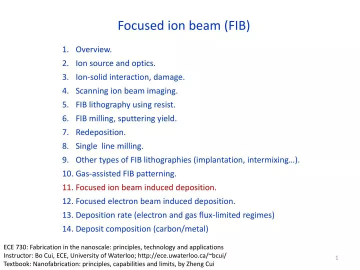
Focused ion beam (FIB) Overview. Ion source and optics. Ion-solid interaction, damage. Scanning ion beam imaging. FIB lithography using resist. FIB milling, sputtering yield. Redeposition. Single line milling. Other types of FIB lithographies (implantation, intermixing…). Gas-assisted FIB patterning. Focused ion beam induced deposition. Focused electron beam induced deposition. Deposition rate (electron and gas flux-limited regimes) Deposit composition (carbon/metal) ECE 730: Fabrication in the nanoscale: principles, technology and applications Instructor: Bo Cui, ECE, University of Waterloo; http://ece.uwaterloo.ca/~bcui/ Textbook: Nanofabrication: principles, capabilities and limits, by Zheng Cui
DualBeam FIB/SEM plus GIS GIS: Gas Injection Systems FEI Dual-Beam system
GIS: Gas Injection Systems 0.5mm GIS positioned above a circuit • Gases are delivered to the sample surface via a needle in close proximity to the surface (50-150m). • Gas pressure is of order 10-5 mbar. • Interaction of ion beam with gas causes either enhanced removal of sample material, or deposition of one of the elements within the gases. • A metal-organic gas is used to deposit metals via ion/electron beam assisted chemical vapor deposition. • An insulator can also be deposited, e.g. SiO2 from tetraethyl orthosilicate (TEOS). • Reactive gases are used to etch samples via reactive ion etching.
FIB assisted (chemical vapor) deposition process Primary ions remaining as impurities Dissociated elements remaining as impurities • Adsorption of gas molecules on substrate • Dissociation/decomposition of gas molecules by the ion beam • Deposition of the material atoms and removal of the organic ligands “Studies of structures elaborated by focused ion beam induced deposition”, Prestigiacomo, MEE 2004.
Gases used for metal, oxide and C deposition W(CO)6 hfac – hexafluoro acetyl acetanoate TMVS – trimethyl vinyl silane • More deposition materials: • Al: Trimethylaminealane (TMAA), 1Torr vapor pressure at 25°C • SiO2: O2 and tetramethoxysilane (TMOS) Si(OCH3)4 • C: phenanthrene
Ion beam assisted deposition • Properties: • Resistivity much higher than bulk value (10-5000) • Carbon contamination • Gallium contamination • Chemistry not well understood
Collision cascade model – Au deposition • In principle, decomposition of precursor gas may take place either in the gas phase or on the surface; but actually deposition rate insensitive to gas pressure, so gas phase decomposition is unimportant. • Deposition go beyond beam spot size with yield higher than would be by only direct ion-molecule collision. • Yield better correlated with energy loss to the nuclei than with energy loss to the electrons. • Therefore, collision cascade has to play an important role in the decomposition. • In the case of gold, sputtering (of excited surface atoms) will occurs for E>3.8eV. • For energy E>0.95eV (dissociation energy of the absorbate), deposition will occur. “Mechanism of ion beam induced deposition of gold”, Melngailis, JVST B, 1994.
Collision cascade model Collision cascade is related to nuclear stopping power, which is closely related to decomposition yield. Electronic stopping power is not related to decomposition yield Stopping power: energy loss per unit travel distance, eV/Å. DMG(hfac): dimethyl gold hexafluoro-acetylacetonate C7H7F6O2Au, liquid at RT. “Mechanism of ion beam induced deposition of gold”, Melngailis, JVST B, 1994.
FIB deposition: role of SE and primary ion Fig. 5. Sketch of reaction zones of different mechanisms involved in IBID. • Though the yield for primary ion induced deposition is low, its contribution is not negligible due to high ion flux (central tip). • SE is most important, causing deposition well beyond beam size. • Next to the beam, both sputtering and deposition (induced by secondary/ sputtered atoms) are important. • At longer dwell time (1ms), gas is depleted at the beam center and net sputtering occurs, leading to a central nano-hole. Fig. 4. SEM images of doughnut-like structures grown at spot mode with 15pA ion beam current (a,b) with a central tip (dwell time 0.1ms, exposure time 20s per spot); (c,d) with a central nanohole (dwell time 1ms, exposure time 20s). 30keV Ga+ FIB using (CH3)3Pt(CpCH3), beam size 13nm “The Complex Mechanisms of Ion-Beam-Induced Deposition”, Chen, JJAP, 2008
Effect of ion species and energy on yield and purity YN=YD-YS Heavier ion, higher yield. Lighter ion, poorer purity, would be worse for e-beam induced deposition. YN=net deposition, YD=deposition, YS=sputtering Melngailis, “Mechanism of ion beam induced deposition of gold”, JVST B, 1994.
Effect of ion incident angle According to collision cascade model, deposition yield should be closely related to sputter yield, as atoms come out of the surface (sputtered away) or excited at the surface (not sputtered away) would induce decomposition. It was found that deposition yield does increase with angle of incidence, but not as fast as milling/sputtering yield. “Focused ion beam induced deposition and ion milling as a function of angle of ion incidence”, JVST B, 1992.
Deposition parameters Dwell time: residence time at one point, desire one monolayer deposition per dwell time. About 0.4s for C; 0.2s for Pt. Refresh time: time between successive dwells at same point Overlap: amount two consecutive points overlap to obtain uniform deposition. typical 25% (positive overlap) to -100% (negative overlap) Ion current: area 5pA/m2
Competition between deposition and sputtering dN=Φη dt1−JS dt2 deposition milling Net deposition 0.1ms Fig. 4. Dwell time vs mean film thickness under ion dose 3nC/μm2, spot size 25nm, and current 207pA. 2.5ms Net milling Fig. 3. Deposited tungsten by FIB with different dwell times from 0.1 to 2.5 ms, and the same ion dose 6nC/μm2, refresh time 1000μs, X and Y step size 71nm and 68nm, beam spot size 25 nm Fu, “Characterization of focused ion beam induced deposition process and parameters calibration”, Sensors and Actuators A, 2001.
Competition between deposition and sputtering W: deposition vs. sputtering W deposited with 15μs dwell and 0.16μm step size, sputtering exceeds deposition. W deposited with 0.3μs dwell and 0.6μm step size J. Mohr and R. Oviedo, 19th ISTFA Proceedings, Nov. 1993, p.391
Deposition limited by gas diffusion and absorption 1pA, beam 7nm NOT limited by gas diffusion under optimal conditions. Effect of the gas precursor nozzle position on nano-rod growth. Limited by diffusion. Li and Warburton, Nanotechnology, 2007
Focused ion beam (FIB) Overview. Ion source and optics. Ion-solid interaction, damage. Scanning ion beam imaging. FIB lithography using resist. FIB milling, sputtering yield. Redeposition. Single line milling. Other types of FIB lithographies (implantation, intermixing…). Gas-assisted FIB patterning. Focused ion beam induced deposition. Focused electron beam induced deposition. Deposition rate (electron and gas flux-limited regimes) Deposit composition (carbon/metal)
Focused electron beam induced deposition Tools: DualBeam FIB/SEM, SEM, Scanning TEM • The overall picture of deposition is similar to focused ion beam induced deposition: • Fast electron excites an adsorbed precursor molecule. • Excited molecule dissociates into volatile and non-volatile components. • The volatile component escapes and leaves behind the non-volatile deposit.
Focused electron beam induced deposition: examples On non-flat surface with high aspect ratio Deposit far from being pure metal, up to 90% impurity (mostly carbon) On flat surface (very high resolution) A topographical map of the world on a flat substrate. A tip grown on a scanning tunneling microscopy probe. High-resolution TEM image of a typical deposit showing a nano-composite material nanometer-sized metal crystals in an amorphous C matrix.
Comparison to FIB induced deposition • No sputtering/material removal, so always pure deposition, unless reactive gas is introduced (then form volatile species) – gas assisted FEB (focused electron beam) etching similar to gas assisted FIB etching. • Deposit has no Ga impurity, but a lot more amorphous carbon. • Worse electrical conductivity, more important to avoid polymerization component in the precursor gas (C-H). • Deposition speed of FIB-ID is 10 that of FEB-ID for reasons not well understood yet. • For low-aspect ratio deposition, FEB-ID is better for high resolution due to small focused electron beam size. • For high aspect ratio nano-rod deposition, FIB-ID is usually better because ion-solid interaction is well localized near the rod-apex, so is the deposition. • Application side, FIB-ID is more mature and is widely used in industry; FEB-ID is essential for DUV mask repair because Ga+ implantation into mask blocks DUV light.
FEB-induced deposition mechanism Ionization cross-section for GeH4 molecules calculated using binary encounter model. Peak at 50-100V. Schematic dissociation cross-section showing typical shape. Dissociation decomposition of precursor gas molecules • Dissociate cross-section peaks at 50-100eV, so low-energy electrons such as secondary electrons play a central role. • Important processes: dissociative electron attachment (DEA), dipolar dissociation (DD). • For high energy primary electrons, due to its large number, dissociative ionization (DI) is important. • Another proof of electron contribution: upon UV irradiation, precursor decomposition yield depends primarily on photoelectron yield of the substrate. Measured and estimated dissociation cross sections for few precursors. Two step dissociation for Fe(CO)5, through intermediate state B. Hagen, “A critical literature review of focused electron beam induced deposition”, JAP 2008.
Contribution from PE, SE and BSE Electron scattering volume Energy spectrum of electrons emitted from substrate PE: primary electron with E=eV SE: secondary electron FSE: forward scattered electron BSE: back-scattered electron For 3D deposit, electrons can cross target-vacuum interface in many different ways. Top view of simulated SE emission sites on a flat substrate, showing spatial distribution. SE/BSE definition: newly generated electrons are called secondary electrons (SE) if their energy upon leaving the substrate is 50eV, and backscattered electrons if >50eV. That is, here SE/BSE is by definition, without strict physical meaning.
Contribution from PE, SE and BSE PE: primary electron with E=eV SE: secondary electron FSE: forward scattered electron BSE: back-scattered electron Simulated energy distribution of SEs and BSEs emitted from a Ge substrate, and the estimated cross-section for the dissociation of WF6. • SE dominates deposition, PE and BSE not negligible. • PE important within electron beam center, especially in the early stage of deposition.
Focused ion beam (FIB) Overview. Ion source and optics. Ion-solid interaction, damage. Scanning ion beam imaging. FIB lithography using resist. FIB milling, sputtering yield. Redeposition. Single line milling. Other types of FIB lithographies (implantation, intermixing…). Gas-assisted FIB patterning. Focused ion beam induced deposition. Focused electron beam induced deposition. Deposition rate (electron and gas flux-limited regimes) Deposit composition (carbon/metal)
Deposition rate dN/dt=0 at steady state N (cm-2): precursor molecule coverage g: sticking factor F (cm-2s-1): gas flux arriving at the substrate N0: available adsorption site density in a monolayer (E) (cm2): dissociation cross section J (electrons s-1 cm-2): current density (s): residence time Assume J = JPE+JBSE+JSE = beam current R(cm/sec): growth rate Vmolecule (cm3): volume of deposited molecule
Deposition rate: two regimes • Ignore desorption (=), two regimes: • Current limited, rate independent of gas flux. • Gas flux limited, rate independent of current density. • In both regimes, height increases with dwell time linearly.
Effect of precursor transport (gas flux) Increasing source-beam distance 10μm-1mm Ip=1000pA E=25keV te=180s Current limited Deposition rate decreases with increasing distance, central structure appears High electron density: columnar growth (beam center). Low electron density: “polymerization” (by peripheral electrons and BSE, current-limited growth)
Deposition rate: two limiting regimes e Intensity profiles (DF TEM)
Substrate-precursor molecular interaction: diffusion, absorption/desorption • Absorption may occur as chemi-sorption or physi-sorption. • The gas molecular arrives at/bombards the surface at a rate of . • Characteristic residence time of precursor molecule on the substrate is . • Longer gives higher probability of dissociation by electrons. • Once deposition starts, becomes that for precursor molecule on deposit surface. • Is a sensitive function of temperature, heating reduces thus deposition rate. For W(CO)6, M=352, at RT and 0.01Torr 10000 times/nm2sec Is the vibration frequency of an adsorbed molecule, Edes is the desorption energy (J).
Effect of heating TEOS Carbon contamination deposition Rate decreases with current due to heating induced desorption. Dwell time fixed at 120sec, slower deposition for C at higher I due to heating.
Deposition diameter Fig. 12. The development of the width of an e-beam deposited structure. Experimental results. Inset shows the width development for short times. Result from a Monte Carlo simulation. Vertical growth is due mostly to direct dissociation by PEs. Lateral growth is due mostly to SEs. In principle, lateral growth should stop once ddepositdbeam+2SE escape length. But BSE can go far away and generate SE there, so diameter can go quite large after long time.
High resolution deposition The mean free path depends on material, here should be a heavy material (high Z) with very short mean free path. • Strategy: • Use high voltage STEM that has small beam spot size, and short deposit time (but then low aspect ratio). • That is, stop deposition before significant lateral widening (by SE) occurs. • STEM: scanning transmission electron microscopy, beam <0.2nm. Stop here
SE spread and deposition size by simulation Monte Carlo simulation on smooth Cu surface with a 200kV electron beam with zero-beam-size Dissociation yield as a function of position from the primary beam
High resolution deposition examples W deposition using high resolution STEM 25ms 2.5s 275ms, 3.5nm Resolution is high, but aspect ratio is low, height/width order of 1.
High resolution deposition examples 4.0nm size 1.0nm size W containing dots with W(CO)6 precursor
Focused ion beam (FIB) Overview. Ion source and optics. Ion-solid interaction, damage. Scanning ion beam imaging. FIB lithography using resist. FIB milling, sputtering yield. Redeposition. Single line milling. Other types of FIB lithographies (implantation, intermixing…). Gas-assisted FIB patterning. Focused ion beam induced deposition. Focused electron beam induced deposition. Deposition rate (electron and gas flux-limited regimes) Deposit composition (carbon/metal)
Deposit composition – carbon/metal • For W deposition using W(CO)6, thermal decomposition (regular CVD process) W(CO)6 + heat -> W(CO)6-n+nCO, CO removed easily by heating to 200oC, leading to pure W. • But for FEB induced deposition, large amount carbon (amorphous with high graphene component) always exists in the deposit when using carbonaceous precursors. • Because electrons aggressively excite/activate many of the atoms in the precursor molecule. • Even precursor is carbon-free, carbon gets into deposit easily from chamber contaminants. Electron energy loss spectra recorded from Pt deposits on a thin film of Si3N4, showing 90% of the deposit is carbon, the ratio is similar to C/Pt ratio in the precursor Pt(CH3)3CH3C5H4.
Non-carbon contamination (Rh deposition using [(PF3)2RhCl]2 Cl F P Rh
Deposit: metallic Rh nano-particles in a lighter amorphous matrix. Z-contrast image • Summary: • FEB deposition is different from thermal (CVD) deposition. • It is closer to electron-ionization mass spectroscopy • The deposit composed of nano-particles in protecting matrix.
Electrical properties of the deposit Typical pure metal resistivity <10cm Resistivity (no C, purer)
How to reduce carbon? • Increase beam current. • Add reactive gas such as H2. • Post-deposition processing – thermal treatment in oxidization environment. Deposition
Effect of beam current on metal content and morphology The metal content as a function of beam current. Co2(CO)8 Me2-Au-tcac CpPtMe Mo(CO)6 • The increase in metal content with beam current can be due to two parallel processes: • Increase in beam current can induce an increase in the desorption of fragments of (initially only partially dissociated) precursor molecules. This can lead to higher concentrations of nonvolatile among others metal components in the final deposit. • E-beam induced heating. A raise in temperature may, for instance, facilitate the desorption of volatile species, as well as change the dissociation mechanism.
Effect of beam current on morphology Higher current, rougher Surface morphologies for high current deposits created with the beam in spot mode. Mo(CO)6 hfac-Cu-VMTS c) Co(CO3)NO Co2(CO)8. Generally, at low beam currents, the deposit is smooth and completely amorphous with high impurity concentration. At high beam currents, the deposit is rougher with irregular shape and is polycrystalline, the crystallites being between 2nm and 8nm in size.
Contaminant-free deposit of GaN in UHV Electron energy loss spectrum Diameter 4nm, height 5nm. Precursor gas is D2GaN3 D2GaN3 + e- -> GaN (solid) + D2 + N2
Proximity effect • Proximity effect is due to backscattering • It leads to deposition over large surface area at the base. • It may cause short circuit. A halo around a deposited tip due to proximity effect as it is known in e-beam lithography. Short circuit?
High aspect ratio structures • It is possible, but not as easy as FIB-induced deposition. • Electron penetrate deep inside the nano-rod and can escape from a point far below the rod apex, causing continuous deposition at points well below the apex. Focused electron beam deposition Tip diameter: 15nm (W-tip) V=120kV, beam diameter = 3nm Focused ion beam deposition, high aspect ratio easy to achieve S. Matsui and T. Ichihashi, APL 53 (1988) 842