Download
1 / 15
150 likes | 223 Views
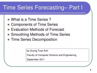
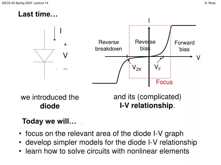
I. I. + _. Reverse bias. Reverse breakdown. Forward bias. V. V. V F. V ZK. Last time…. Focus. and its (complicated) I-V relationship. we introduced the diode. Today we will…. focus on the relevant area of the diode I-V graph

E N D
I I + _ Reverse bias Reverse breakdown Forward bias V V VF VZK Last time… Focus and its (complicated) I-V relationship. we introduced the diode Today we will… • focus on the relevant area of the diode I-V graph • develop simpler models for the diode I-V relationship • learn how to solve circuits with nonlinear elements
DIFFERENT MODELS, DIFFERENT USES • We will consider 4 different diode I-V models with varying degrees of detail. • Use most realistic model only for very precise calculations • Use simpler models to find basic operation, gain intuition • Sometimes one model may lead to an “impossible” situation: use a different (more realistic) model in this case
I + _ V REALISTIC DIODE MODEL I V • Here, VT is “thermal voltage”: VT = (kT)/q ≈ 0.026 V @ 300oK • (q is electron charge in C, k is Boltzmann’s constant, and T is the operating temperature in oK) • Equation is valid for all modes of operation considered • You might need a computer to solve the nonlinear equation this model can create
I + _ V IDEAL DIODE MODEL I I Forward bias + _ V Reverse bias V • Diode either has negative voltage and zero current, or zero voltage and positive current • Diode behaves like a switch: open in reverse bias mode, closed (short circuit) in forward bias mode • Guess which situation diode is in, see if answer makes sense
I + _ V LARGE-SIGNAL DIODE MODEL I I + + - Forward bias VF V Reverse bias V VF - • Diode either has voltage less than VF and zero current, or voltage equal to VF and positive current • Diode behaves like a voltage source and switch: open in reverse bias mode, closed in forward bias mode • Guess which situation diode is in, see if answer makes sense
I + _ V SMALL-SIGNAL DIODE MODEL I I + slope = 1/RD + - VF Forward bias Reverse bias V V RD VF - • Diode either has voltage less than VF and zero current, or voltage greater than VF and positive current depending on V • Diode behaves like a voltage source, resistor and switch: open in reverse bias mode, closed in forward bias mode • Guess which situation diode is in, see if answer makes sense
IL INL + VL - + VNL - Nonlinear element Linear circuit SOLVING CIRCUITS WITH NONLINEAR ELEMENTS Look at circuits with a nonlinear element like this: A nonlinear element with its own I-V relationship, attached to a linear circuit with its own I-V relationship. • Equations we get: • IL = fL(VL) (linear circuit I-V relationship) • INL = fNL(VNL) (nonlinear element I-V relationship) • INL = -IL • VNL = VL
SOLVING CIRCUITS WITH NONLINEAR ELEMENTS • Our 4 equations • IL = f(VL) (linear circuit I-V relationship) • INL = g(VNL) (nonlinear element I-V relationship) • INL = -IL • VNL = VL • can easily become just 2 equations in INL and VNL • INL = -fL(VNL) • INL = fNL(VNL) • which we can equate and solve for VNL, or… • graph the two equations and solve for the intersection.
LOAD LINE ANALYSIS To find the solution graphically, INL graph the nonlinear I-V relationship, -fL(VNL) graph the linear I-V relationship in terms of INL and VNL (reflect over y-axis), x fNL(VNL) VNL and find the intersection: the voltage across and current through the nonlinear element.
EXAMPLE 1 kW Find VNL. Assume realistic diode model with I0 = 10-15 A. INL + _ + _ IL + - 2 V VNL VL • IL = (VL- 2) / 1000 • INL = -IL • VNL = VL Either substitute into 3. and solve or determine graphically that VNL = 0.725 V
EXAMPLE REVISITED 1 kW Find VNL. Assume small-signal diode model with VF = 0.7 V and RD = 20 W. INL + _ + _ IL + - 2 V VNL VL • IL = (VL- 2) / 1000 • INL = (VNL – 0.7) / 20 or INL = 0 • INL = -IL • VNL = VL Either substitute into 3. and solve (VNL – 0.7) / 20 = -(VNL- 2) / 1000 or determine graphically that VNL = 0.725 V
ONE MORE TIME 1 kW Find VNL. Assume small-signal diode model with VF = 0.7 V and RD = 20 W. INL + _ + _ IL + - -2 V VNL VL • IL = (VL- - 2) / 1000 • INL = (VNL – 0.7) / 20 or INL = 0 • INL = -IL • VNL = VL Either substitute into 3. and solve 0 = -(VNL- - 2) / 1000 or determine graphically that VNL = -2 V