Download
1 / 11
110 likes | 229 Views
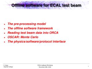
ECAL @ the DESY test beam. On behalf of the French and British groups A status report on the activities at the DESY test beam With a special thank you to the Japanese group for borrowing and installing the drift chambers. DC1. DC2. DC3. ECAL. DC4. beam. VME card. ECAL. beam.

E N D
ECAL @ the DESY test beam On behalf of the French and British groups A status report on the activities at the DESY test beam With a special thank you to the Japanese group for borrowing and installing the drift chambers
DC1 DC2 DC3 ECAL DC4 beam
VME card ECAL beam
Detector slab Carbon fiber + tungsten structure
ECAL readout overview Only upper slab installed = 36 * 6 = 216 channels/layer *2 ~3000 r/o channels
Online plots Online pedestal monitor • Data taking: • 100 pedestal events followed by • 1000 beam events - random trigger designed into the firmware - up to 16 backplane trigger input • used at present to monitor • scintillator counters • Online display pedestal and noise of 216*8=1728 channels Online noise monitor
Top e- 3 GeV Front Side |- 7 X0 -|
Top e- 3 GeV Front Side |- 7 X0 -| 3 X0
Settings for data taking: • -trigger delay ~120 ns, shaping time = 180-190 ns hold @ ~ 60ns • Result from latency scan hold should be set between (0-20)*6.25ns • Current set: 10*6.25ns • First look at the data: • No calibration applied spread of response from various pads <10% • Ped subtracted • Threshold applied MIP ~3MIP
Comparison of the results with the cosmics calibration performed in LAL
Schedule 7 - 8 Feb: TDC CRC tuning 9 - 11 Feb: Beam scan over the whole detector 12 - 15 Feb: High statistics scan of boundaries between wafers 16 - 25 Feb: Angle and energy scan 1-2-3 GeV, 0,10,20,30 deg 25 Feb: Detector in parking position Mar - Apr: No measurements foreseen Success with your program from the HCAL group