Download

1 / 31
330 likes | 540 Views
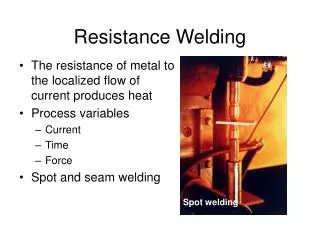
Resistance and Solid-State Welding Processes. Chapter 32. 32.1 Introduction. 32.2 Theory of Resistance Welding. Basic Resistive Welding. FIGURE 32-1 The basic resistance welding circuit. Resistive Welding Temperature Distribution. FIGURE 32-2 The desired temperature distribution across

E N D
Resistance and Solid-State Welding Processes Chapter 32
Basic Resistive Welding FIGURE 32-1 The basic resistance welding circuit.
Resistive Welding Temperature Distribution FIGURE 32-2 The desired temperature distribution across the electrodes and workpieces during resistance welding.
Current and Pressure for Resistive Welding FIGURE 32-3 A typical current and pressure cycle for resistance welding. This cycle includes forging and postheating operations.
Schematic of Resistive Welding FIGURE 32-4 The arrangement of the electrodes and workpieces in resistance spot welding.
Microstructure of a Resistance Weld FIGURE 32-5 A spot-weld nugget between two sheets of 1.3-mm (0.05-in.) aluminum alloy. The nugget is not symmetrical because the radius of the upper electrode is greater than that of the lower electrode. (Courtesy Lockheed Martin Corporation, Bethesda, MD.)
Tear Test FIGURE 32-6 Tear test of a satisfactory spot weld, showing how failure occurs outside of the weld.
Resistive Welder FIGURE 32-7 Single-phase, air-operated, press-type resistance welder with microprocessor control. (Courtesy Sciaky Inc., Chicago, IL.)
Spot Welding Seams FIGURE 32-8 Seam welds made with overlapping spots of varied spacing. (Courtesy Taylor-Winfield Corporation, Brookfield, OH.)
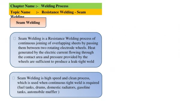
Schematic of Seam Welding FIGURE 32-9 Schematic representation of the seam-welding process. those
Tube Welding FIGURE 32-10 Using high- Squeeze roll frequency AC current to produce a resistance seam weld in buttwelded tubing. Arrows from the contacts indicate the path of the high-frequency current
Projection Welding FIGURE 32-11 Principle of projection welding (a) prior to application of current and pressure and (b) after formation of the welds.
Cold Welding FIGURE 32-12 Small parts joined by cold welding. (Courtesy of Koldweld Corporation, Willoughby, OH.)
Roll Welding FIGURE 32-13 Examples of roll-bonded refrigerator freezer evaporators. Note the raised channels that have been formed between the roll-bonded sheets. (Courtesy Olin Brass, East Alton, IL.)
Friction Welding FIGURE 32-14 Sequence for making a friction weld. (a) Components with square surfaces are inserted into a machine where one part is rotated and the other is held stationary. (b) The components are pushed together with a low axial pressure to clean and prepare the surfaces. (c) The pressure is increased, causing an increase in temperature, softening, and possibly some melting. (d) Rotation is stopped and the pressure is increased rapidly, creating a forged joint with external flash.
Schematic for Friction Welding FIGURE 32-15 Schematic diagram of the equipment used for friction welding. (Courtesy of Materials Engineering.)
Inertia Welding FIGURE 32-16 Schematic representation of the various steps in inertia welding. The rotating part is now attached to a large flywheel.
Examples of Friction Welding FIGURE 32-17 Some typical friction-welded parts. (Top) Impeller made by joining a chrome–moly steel shaft to a nickel–steel casting. (Center) Stud plate with two mild steel studs joined to a square plate. (Bottom) Tube component where a turned segment is joined to medium-carbon steel tubing. (Courtesy of Newcor Bay City, Division of Newcor, Inc., Royal Oak, MI.)
Stir Welding FIGURE 32-18 Schematic of the friction-stir welding process. The rotating probe generates frictional heat, while the shoulder provides additional friction heating and prevents expulsion of the softened material from the joint. (Note: To provide additional forging action and confine the softened material, the tool may be tilted so the trailing edge is lower than the leading segment.)
Example of Stir Welding FIGURE 32-19 (a) Top surface of a friction-stir weld joining 1.5- mm- and 1.65-mm-thick aluminum sheets with 1500-rpm pin rotation. The welding tool has traversed left-to-right and has retracted at the right of the photo. (b) Metallurgical cross section through an alloy 356 aluminum casting that has been modified by friction-stir processing.
Schematic of Ultrasonic Welding FIGURE 32-20 Diagram of the equipment used in ultrasonic welding
Explosive Welding FIGURE 32-21 (Left) Schematic of the explosive welding process. (Right) Explosive weld between mild steel and stainless steel, showing the characteristic wavy interface.