Download
1 / 21
210 likes | 454 Views
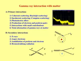
1th Workshop on “Photo Detection” June 13 - 14 , 2007 Perugia, Italy. Photodetector requirements for gamma ray imaging with scintillation crystals Roberto Pani INFN and Sapienza-University of Rome Italy. Scintillation crystal readout technique. Light Sharing. Individual Coupling.

E N D
1th Workshop on “Photo Detection” June 13 - 14 , 2007 Perugia, Italy Photodetector requirements for gamma ray imaging with scintillation crystals Roberto Pani INFN and Sapienza-University of Rome Italy
Scintillation crystal readout technique Light Sharing Individual Coupling Continuous crystal Pixellated crystal
Individual coupling technique Munich APD PET* 4 x 8 APD Array (Hamamatsu Photonics) 2 x 2 x 6 mm3 LSO individual coupled Intrinsic FWHM ~ 1.2 mm * Courtesy of Roger Lecomte – Université de Sherbrooke (Québec, Canada)
Individual coupling technique • High packing fraction > 80% • Spatial resolution limited by crystal pixel size ( 1mm tomography, > 1mm planar image) • Electronic readout up to 20000 chains (SPET) • Single photoelectron readout not needed • Low noise to allow 140 keV photon energy detection • High gain (104 or more) not needed • Energy resolution depending on scintillation crystal / photodetector
X & Y Position Centroid Algorithm Si i ni Position: X = Si ni E = Si ni Energy: Light sharing technique Scintillation light flash on photocathode Anode array (Hamamatsu H8500) Charge distribution sampling by anode array 1 2 3 4 5 6 7 8 k 1 2 3 4 5 6 7 8 … i
Image PSF1mm FWHM oneγ-ray interaction Manyγ-rayinteractions Scintillation light PSF 15 mm FWHM Position linearity Co57 pulse height analisys Position determination in light sharing technique
Light sharing technique • Spatial resolution limited by crystal pixel size ( scintillation array) • Spatial resolution not limited for continuous crystal • Low number of electronic chains • Single photoelectron readout needed • Energy resolution depending on scintillation crystal /photodetector • High gain ( >104 ) is needed • Timing/rise time < 500 ps for ToF
Point Spread Function and critical angle c Planar crystal / PMT glass window Pixellated crystal / PMT glass window Light output angle < 45°
Pixellated scintillation crystal NaI:Tl 1m m x 1mm x 4 mm + H8500 MAPMT Poor energy resolution ~ 14% Pixel Spatial resolution < 1.3 mm Image Spatial resolution > 1.3 mm
Continuous scintillator crystal 1.5 mm step scannig – 0.4 mm Ø Tc99m point source LaBr3:Ce 49 mm x 49 mm x 4 mm + 3 mm glass window H8500 MAPMT • Best Values: • Energy resolution = 9.6 % (@ 1000V) • Overall Spatial Resolution= 1.1 mm • Intrinsic Spatial Resolution= 1.0 mm Very good linearity !!!
Detector assembly: • MAPMT Hamamatsu H8500 • LEGP collimator • (1.5 mm hole, 22 cm lenght) • Multi-anode read-out • Crystal samples: • LaBr3:Ce continuous, 5mm thick • NaI:Tl array, 1.1mm pixel 1.3 pitch • MTF for Continuous Crystal • Spatial Resolution limited to LEGP • Enhancement in Contrast - increased AUC (Area Under Curve) • NO restrictions in image digitization (Nyquist frequency not limited from image pixel) • Continuous position response • Increased detection efficiency Modulation Transfer Function
Scintillation crystal: requirements for SPECT (@140 keV) • Z 40 →Photofraction greater than 70% • High density (> 3 gr/cc) →Reduction of crystal thickness to obtain 80-90% efficiency ( important for light collection) • Refraction index close to 1.5 →To avoid light loosing due to critical angle (continuous crystal) • Decay time 1 ms→To obtain 200 kHz max. • High luminous efficiency (> 20000 at suitable wavelength) → To improve: Decoding crystal pixel in scintillation array • Spatial resolution, in continuous crystal • Energy resolution. • Lowafterglow for high counting rate There are few predictions if energy resolution or light output dominates the intrinsic spatial resolution in light sharing
Scintillation crystal: requirements for PET (@ 511 keV) • Z 50 →Photofraction greater than 30% • High density ( >7 gr/cc) →To obtain, in 30 mm crystal length, 50% coincidence efficiency and reduction parallax error for small animal imaging. Scintillation decay time 300 ns →To allow good coincidence time resolution. Time resolution better than 0.5 ns can reduce random coincidences (50 % in a 3D PET) and time of flight can be realized. • High luminous efficiency > 8000 ph/MeV → • To enable block detectors with a greater number of pixel (from • 8 8 BGO to 16 16 LaBr3(Ce) crystal pixel/module). • Improvementin energy resolution reduces scatter background (25% • Compton scattering / 25% “true” events in a 3D PET). • Lowafterglow for high counting rate
Energy Resolution • Intrinsic Scintillation Contribute • Non homogeneities • Non proportionality of scintillation response Electronic noise Photodetector and preamplifier system [Equivalent noise charge – E. Gatti, NIM Phys Res 1990] Statistical generation of the signal Nph: number of photons in a scintillation flash a : worsening of the Poisson behaviour h : Quantum Efficiency
Intrinsic Scintillator Energy Resolution NaI(Tl)A LaBr3(Ce)B A – Prescott and Narayan, NIM A, 75 (1969) B – G.Bizarri, IEEE TNS, Vol 53,02 (2006) Luminosity (phe @ 662keV - PMT 25% QE) W.Moses, NIM A, 487 (2002)
1 inch 1 inch Is the QE really useful? 1° PMT HIGH QE: Hamamatsu R7600-200 Crystal Test: LaBr3:Ce Cylinder (½”Ø ½” thickness) • QE max. = 41.6 % @ 380 nm • Number of dinode = 10 • Gain= 2.0 E+06 @ HV= -700 V
2° PMT HIGH QE: Hamamatsu R8900-00-C12 • QE max. = 42 % @ 350 nm • Number of dinode = 12 • Gain= 1.0 E+06 @ HV= -800 V Is the QE really useful? Pulse heigh Resolution & Coincidence Resolving Time: Crystal TEST: LSO 4 x 4 x 20 mm3 Source : Na22 (Eg @ 511keV) PMT position *Courtesy of Hamamatsu Photonics K.K. (Iwata City - Japan)
Critical Angle & Q.E. :MC Simulation GEANT 4 • Scintillation crystal : LaBr3:Ce continuous crystal 50 x 50 x 4 mm3 ( white entrance face – black edges) • 8 8 Photodetector array ( 6.0 mm pitch) • 140 keV photon energy No glass window Q.E = 0.22 –Phe n°=1860 3 mm glass window Q.E = 0.22 – Phe n°=1153 No glass window Q.E = 0.60 – Phe n° = 5102 S.R.= 0.75mm E.R. = 2.3% ( 5.1 % including intrinsic energy resolution of LaBr3:Ce) S.R.=0.82 mm E.R. = 5.1 % ( 6.9 % including intrinsic energy resolution of LaBr3:Ce) S.R.= 0.60 mm E.R. = 1.4 % ( 4.8 % including intrinsic energy resolution of LaBr3:Ce)
Conclusion • LaBr3:Ce seems a very promising crystal for SPET ( PET ToF) application • Light sharing on continuous crystal requires position sensitive photodetectors with superior performances • Intrinsic energy resolution of scintillators can seriously limit the energy resolution response of a high Q.E. photodetectors • Removing glass window( critical angle) in scintillator coupling, could strongly enhance imaging performances