Download
1 / 10
100 likes | 259 Views
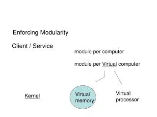
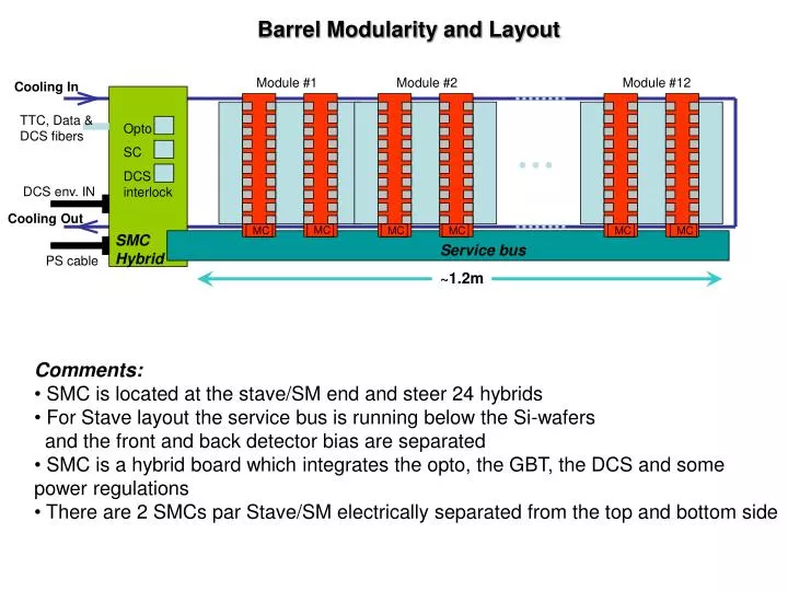
Module #1. Module #2. Module #12. Cooling In. TTC, Data & DCS fibers. Opto. SC. DCS interlock. DCS env. IN. Cooling Out. SMC Hybrid. Service bus. PS cable. ~1.2m. MC. MC. MC. MC. MC. MC. Barrel Modularity and Layout. Comments:

E N D
Module #1 Module #2 Module #12 Cooling In TTC, Data & DCS fibers Opto SC DCS interlock DCS env. IN Cooling Out SMC Hybrid Service bus PS cable ~1.2m MC MC MC MC MC MC Barrel Modularity and Layout • Comments: • SMC is located at the stave/SM end and steer 24 hybrids • For Stave layout the service bus is running below the Si-wafers • and the front and back detector bias are separated • SMC is a hybrid board which integrates the opto, the GBT, the DCS and some power regulations • There are 2 SMCs par Stave/SM electrically separated from the top and bottom side
Interlock Overview • Cooling Interlock: Power cut of the corresponding stave cooling loop • Same scheme as the current SCT • Justification: Protection against cooling failure • Action: Interlock the LV and HV of the stave • Module Interlock: Disable local/global power • Must be different scheme since PS is locally distributed • Justification: Protection against local excess heating (runaway or cooling contact pb) • Action: Interlock the LV and HV of the stave • NB: Scheme may be different for serial powering and DC-DC • SMC Interlock: Disable Power on SMC and on Stave • Justification: Protection against excess heating on SMC card • Action: Interlock the LV and HV of the stave
SMC top DCS ADC & IR DCS on SMC PP1 PS crate – Option 3 Top-side Stave Power-DCS cable Option 3 requires SMC top SMC bottom 3 twisted pair/SMC Connector modularity opened 6 twisted and independent DCS/interlock lines PP1 SMC bot Bottom-side Stave Power-DCS cable 23 NTC lines + 1 line Ref To PS-DCS-Interlock Option 3 1 NTC 2 cooling NTCInterlock 3 env. (NTC) lines or 1 RH sensor
Interlocks - Proposed scheme between Stave and PS Stave Supply / Reading – 2 twps PS Crate Cooling x2 I-box DCS Top side LV PS Top Modules SC-I LV PS Bot SMC HV PS Top X 12? Bottom side Modules SC-I HV PS Bot X 12? SMC Case of DC-DC scheme • NB: • Barrel SP scheme requires 4 LV PS (2 for SMC top & bot, 2 for modules top & bot) • Endcap SP scheme requires 8 LV PS (twice the barrel for better matching in efficiency) • Barrel HV may need up to 12 individual biasing channels per stave side – Not defined yet! • EC HV may need up to 9 individual biasin channels per petal side – Not defined yet!
Combining Interlocks at PS crate – Serial Powering Top-side Stave Power-DCS cable PS Crate NTC-Mod (option3) NTC-Cooling I-box DCS NTC-SMC I-Cooling/Mod I-SMC-Bot I-SMC-Top LV Mod PS Top LV Mod PS Bot I-Modue Top LV SMC PS Top LV SMC PS Bot I-Modue Bot HV PS Top X 12? HV PS Bot X 12? Bottom-side Stave Power-DCS cable • Note that in that scheme it is proposed to get all the NTC-cooling interlock via the top SMC card • Reason is lo leave 3 twisted and independent lines for RH sensors (if needed)
Module Interlock on SMC SC – Serial Powering OR OVER HEAT INTERLOCK REF +V +V GND GND GND GND GND 1 interlock signal/ super-module IC on SMC HYBRID Stave / SM REGISTER TRIPLE VOTE LOGIC + THRESHOLD from DAC with Triple vote logic D F/F NTC NTC NTC - NTC Enable DAC with Triple vote logic 1 2 3 24 CLEAR GBT DCS in ADC 1 ADC 12bits multiplexed RESISTORS REF Asic either with GBT SCA or separated
Combining Interlocks at PS crate – DC-DC (option 1) Top-side Stave Power-DCS cable PS Crate NTC-Mod (option3) NTC-Cooling I-box DCS NTC-SMC I-Cooling/Mod I-SMC-Bot I-SMC-Top LV PS Top LV PS Bot HV PS Top X 12? HV PS Bot X 12? Case of DC-DC scheme Bottom-side Stave Power-DCS cable • NB: Module interlock is steered locally on the stave ( No action on HV): • Either on the SMC where all the LV stave side is interlocked • Or on the MC where each hybrid interlock is steered locally – Interlock the supply on the FE
Module Interlock on Hybrid – DC-DC (option 1) +V GND FE FE FE FE Integrated into MCC + 2.5V FE FE Threshold DAC FE FE NTC + FE FE temp FE FE - GND FE FE Module Interlock FE FE FE FE D F/F En/Dis Interlock From DAC FE FE Clear En/Dis DC-DC From DAC MCC-DCS & Interlock En/Dis DC-DC Stage1 DC-DC Stage 1 En/Dis +2.5V +12V
Combining Interlocks at PS crate – DC-DC (option 2) Top-side Stave Power-DCS cable PS Crate NTC-Mod (option3) NTC-Cooling I-box DCS NTC-SMC I-Cooling/Mod I-SMC-Bot I-SMC-Top LV PS Top I-Modue Top LV PS Bot HV PS Top X 12? I-Modue Bot HV PS Bot X 12? Module interlock inputs for LV and HV at PS crate Bottom-side Stave Power-DCS cable Same module interlock scheme as serial powering
Summary • The interlock scheme is dependent upon the powering option: • Consequence at the PS crate more LV for serial powering and for Endcap + SP • Serial Powering have to use and depend upon a DCS chip on the SMC card for the module interlock and survey • DC-DC may use MC DCS to steer locally on the hybrid the temperature interlock NB: Using the GBT-SCA link on the SMC may lead to additional hardware design at the BOC Slow Control Manager