Download
1 / 57
570 likes | 710 Views
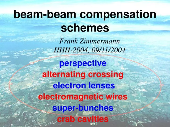
beam-beam compensation schemes. Frank Zimmermann HHH-2004, 09/11/2004. perspective alternating crossing electron lenses electromagnetic wires super-bunches crab cavities. (1) perspective. historical attempts of beam-beam ‘simulation’ & compensation.

E N D
beam-beam compensation schemes Frank Zimmermann HHH-2004, 09/11/2004 perspective alternating crossing electron lenses electromagnetic wires super-bunches crab cavities
historical attempts of beam-beam ‘simulation’ & compensation • 4-beam collisions at DCI ~1970charge neutralization; limited by collective instabilities (J.Augustin et al., Y.Derbenev) • nonlinear lens at ISR, 1975‘simulation’ of head-on collision, copper bars with 1000 A current (E. Keil, G. Leroy) • octupoles compensating BB tune spread for LEP, 1982 (S. Myers) • octupoles at VEPP-4/-2M & DAFNE, 1986, 2001(A. Temnykh, M. Zobov) • plasma compensation for linear & muon colliders, 1988 (D. Whittum, A. Sessler et al.) • Tevatron Electron Lens, FNAL, operational since 2001compensating intra-&inter-bunch tune spread(E.Tsyganov, 1993 V. Shiltsev, 1998) octupoles in LHC?
and LHC: 4 primary IPs 30 long-range collisions per IP 120 in total compensation can act on either head-on or long-range collisions, or on both
long-range beam-beam collisions • perturb motion at large betatron amplitudes, where particles come close to opposing beam • cause ‘diffusive aperture’ (Irwin), high background, poor beam lifetime • increasing problem for SPS, Tevatron, LHC,... that is for operation with larger # of bunches
experience from Tevatron Run-II “long-range beam-beam interactions in Run II at the Tevatron are the dominant sources of beam loss and lifetime limitations of anti-protons …” (T. Sen, PAC2003) ey LR collisions reduce the dynamic aperture by about 3s to a value of 3-4s; little correlation between tune footprint and dynamic aperture drop in ey for first 4 pbar bunches after injection; asymp- totic emittance is measure of their dynamic aperture time
crossing scheme D. Neuffer, S. Peggs: “BEAM-BEAM TUNE SHIFTS AND SPREADS IN THE SSC: HEADON, LONG RANGE, AND PACMAN CONDITIONS,” SSC-63, Apr 1986. Proposal of alternating crossing at two IPs, which cancels the linear part of the long-range beam-beam tune shift and reduces bunch-to-bunch tune spread. Alternating planes of crossing at IP1 & 5 and IP2 & IP 8 were adopted as LHC baseline (W. Herr, CERN/SL/90-06 (AP) (1990)). Since a beam screen is to be installed in the final triplet quadrupoles for vacuum reasons, the orientation of the LHC crossing planes will be frozen for each IP. Alternative crossing schemes would offer other advantages, like vanishing vertical dispersion (xx), easier long-range beam-beam com- pensation (yy), or equal background in the different experiments(xx or yy). They might also prove intrinsically more stable?! Another option would be inclined hybrid crossing (K. Takayama et al.).
LHC tune “footprint” due to head-on & long-range collisions in IP1 & IP5 (Courtesy H. Grote) LR vertical crossing head-on LR horizontal crossing
total LHC tune “footprint” for regular and “PACMAN” bunch (Courtesy H. Grote) tune footprints of nominal & PACMAN bunches similar thanks to alternating crossing LR collisions ‘fold’ the footprint!
diffusion rate (log scale) as a function of amplitude LHC centre of other beam here tunes w/o beam-beam were held constant diffusive aperture with xx or yy crossing diffusive aperture with alternating crossing comparing xy, xx and yy crossing for two working points
weak-strong beam-beam simulations for different crossing schemes in LHCkeeping the same 0-amplitude tunes
xy xy w/o HO xx w/o HO, xx yy,yy w/o HO Simulated diffusion rate as a function of start amplitude for XX, XY and YY crossing with LR only and with the combined effect of LR and SR collisions, for the same 0-amplitude tune 0.30268, 0.31268; start amplitudes x=y.
xx, yy, and xy crossing in LHC IPs 1 & 5 w & w/o HO @ different y tunes varied in steps of 0.005
qc=200 mrad qc=285 mrad [Qy]=64 [Qy]=64 simulated LHC diffusive aperture for nominal & reduced crossing angle vs. Qy, x=y qc=285 mrad qc=200 mrad [Qy]=63 [Qy]=63
qc=285 mrad qc=285 mrad [Qy]=64 [Qy]=63 simulated LHC diffusive aperture for nominal & reduced crossing angle vs. Qy, y=0 (only x amplitude nonzero), in this case xx and yy crossing are always stable, and diffusive aperture found only for xy crossing
xx xy frequency maps for nominal LHC tunes yy thanks to Yannis Papaphilippou for his help in calculating frequency maps!
xx xy frequency maps for QY lower by 0.01 (~on coupling resonance) yy thanks to Yannis Papaphilippou for his help in calculating frequency maps!
result of these simulations: • in all cases diffusive aperture is larger • for equal-plane crossing • possible explanation: • different ‘folding’ since xy crossing • cancels dodecapole and 20-pole terms; • & • (2) twice the number of resonances • for xy crossing
2nd generation BBLR in the CERN SPS can model various LHC crossing schemes G. Burtin, J. Camas, J.-P. Koutchouk, et al.
approximations of XY, XX, and YY crossing in the SPS experiment BBLR2x on (strength x2) beam xx BBLR1 off beam BBLR2x on x bump -23 mm BBLR1 on “xy” beam x bump -23 mm BBLR2x off “xy-2” & (strength x2) BBLR1 on (strength x2) yy x bump -23 mm
experimental result: beam lifetime measured for the three SPS wire configurations and w/o BBLRs diffusive aperture simulated for the three SPS wire configurations experiment simulation simulated diffusive aperture for XX crossing is 10% larger than for ‘quasi-XY’ or ‘quasi-YY’ crossing measured beam lifetime is best for XX crossing, second best for ‘quasi-YY’ crossing, lowest for ‘quasi-XY’ crossing; the case w/o BBLR is similar to ‘quasi-XY’ , - so the equal-plane crossing actually improve the lifetime lifetimes in this experiment are comparable to lifetimes w/o BBLR we need higher wire current or shorter distances for better resolution (tonight!)
SPS MD tonight BBLR1 (rotated) & BBLR2 (45 degree) beam J.-P. Koutchouk = inclined hybrid crossing! (K. Takayama et al.)
Fermilab Tevatron Electron Lens V. Shiltsev designed to compensate beam-beam tune shift of pbars current: ~1-3 A solenoid field: 3.5 T rms radius: 0.66 mm length: 2 m in operation since 2001
beam-beam compensation at Tevatron assumes installation • of two electron lenses with pulsed and variable currents • multiple purposes: • reduce bunch-by-bunch tune variation • compensation also at injection • reduction of intra-bunch tune spread • spring 2001 installation of 1st TEL • 1st studies 2001-2002 • tune shifts of DQ=+0.008 with 3A e- beam • 10-kV e- gun, 3.4 mm diameter, 2 m interaction length • critical factors: a) transverse profile of e- beam (various guns) • uniform, Gaussian, flat-top + Gaussian tails • b) electron-beam alignment
2002: TEL was found to be effective for dc beam cleaning, in routine operation (avoids quenches when beam is dumped) 2003: 1st demonstration of beam-beam compensation TEL slowed down emittance growth of pbar bunch when ‘scallops’ were present effect of TEL not well controlled precise centering of pbar and e- beam difficult since different e- and pbar bunch length yield different BPM response pbar orbits can migrate by 0.5 mm over 12 hours fabrication of 2nd TEL in collaboration with IHEP (Protvino) is underway, completion end of 2004
Long-Range Beam-Beam Compensation for the LHC • To correct all non-linear effects correction must be local. • Layout: 41 m upstream of D2, both sides of IP1/IP5 current-carrying wires Phase difference between BBLRC & average LR collision is 2.6o (Jean-Pierre Koutchouk)
simulated LHC tune footprint with & w/o wire correction • .16s • .005s • .016s Beam separation at IP (Jean-Pierre Koutchouk, LHC Project Note 223, 2000)
motivation long-range collisions cause a large diffusion and proton losses - effect of SPS BBLR wire resembles LHC long-range collisions -hence we can study LHC long-range collisions and their compensation in the SPS simulation with WSDIFF simulation with WSDIFF SPS wire LHC beam diffusive aperture
early in 2002 a single 1-wire BBLR was installed in the SPS each BBLR consists of 2 units, total length: 2x0.8+0.25=1.85 m
2002/2003 MDs • the first BBLR allowed us to model the effect of SPS long-range collisions in the SPS and to benchmark the simulations • 6 MDs were performed in 2002 and 2003 • we observed lifetime reduction, beam losses, and emittance shrinkage, tune shift, orbit distortion, enhanced decoherence; we scanned both the beam-wire distance and the wire current,… • results were published in two reports: CERN-AB-2004011-ABP and LHC-Project-Report-777
measured vs. predicted changes in orbit & tunes induced by SPS beam-beam compensator y orbit change J. Wenninger x tune change y tune change
emittance shrinkage , dynamic aperture, lifetime drop & diffusion induced by SPS beam-beam compensator WEPLT045 J. Wenninger, J.-P. Koutchouk, et al. aperture vs. wire current aperture vs. separation diffusion measurement lifetime vs. separation
for 2004 two novel 3-wire BBLRs were built; one of these is installed in LSS5 close to the 1st BBLR; the 2nd new device is being refurbished, after a vacuum leak, for installation in LSS2
LSS5 G. Burtin remotely movable in Y by 5 mm! installed since July
SPS BBLR MDs in 2004 29./30.07.04 compensation of BBLR1 by BBLR2, mismatched emittance to 4-6 mm, scan compensator current and position, tune scans around SPS & LHC tunes 26.08.04 test of crossing schemes HH, VV, and “pseudo-VH”,tune scan around LHC tunes 02.09.04 compensation of BBLR1 by BBLR2, “scaled” with original emittance at smaller distance
measured BBLR compensation efficiency vs. working point - scan around LHC tunes we scanned QY w/o BBLRs, with BBLR1 only, and with BBLR1 & BBLR2 30.07.04 3rd 10th 7th 4th nearly perfect compensation what happens here? compensate BBLR1 by BBLR2
02.09.04 ‘scaled’ experiment: measured beam lifetime ~69 min. ~36 min. ~61 min. LHC tunes J.-P. Koutchouk
superbunch hadron collider K. Takayama et al., PRL 88, 14480-1 (2002) x-y crossing or 45/135 degree crossing