Download
1 / 43
430 likes | 546 Views
Profile Coordinate Metrology Based on Maximum Conformance to Tolerances. Dr. Ahmad Barari ahmad.barari@uoit.ca. Faculty of Engineering and Applied Science University of Ontario Institute of Technology Oshawa, Ontario, Canada.

E N D
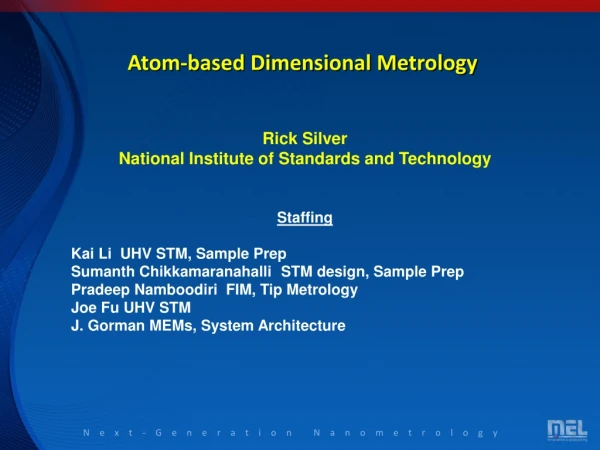
Profile Coordinate Metrology Based on Maximum Conformance to Tolerances Dr. Ahmad Barari ahmad.barari@uoit.ca Faculty of Engineering and Applied Science University of Ontario Institute of Technology Oshawa, Ontario, Canada CMSC - Coordinate Metrology Systems Conference (CMSC 2011), Phoenix, Arizona, 25 – 28 July 2011
pi : i th Measured point Point Measurement Planning (PMP) Tolerance envelope ri Substitute Geometry Estimation (SGE) pi ei Substituted Geometry in the Reference coordinate System εTi εCi Deviation Zone Evaluation (DZE) Desired Geometry in the Reference coordinate System f(e) The Best Substituted Geometry e Probability Density Function of Geometric Deviations Three Basic Computation Tasks in Coordinate Metrology
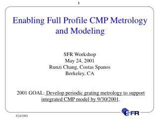
Integration Inspection System: Current Research and Final Goal DZE PMP SGE PMP SGE DZE a) Sequential tasks in traditional coordinate metrology b) Recent research on integration of tasks DZE Design & Manufact. Data PMP SGE DZE d) Integrated Inspection System PMP SGE c) Integrated computational tasks
G″ ΔG′(G″) pi ″ Δ(pi′,G″) Geometric Deviations GNominal geometry G′Actual geometry G″Substitute geometry G*Optimum substitutegeometry pi' G' εi G* Y pi G X Z Six-DOF rigid body transformation Fitting Process
Deviation Zone Evaluation of a Single Geometric Feature The Best Substituted Geometry Substitute Geometry pi ei pi* Objective Function Desired Geometry in the Reference coordinate System DG: Desired geometry Geometric Deviation T: Transformation matrix pi: i th measured point pi*: Corresponding point ni: normal vector at the corresponding point
Residual Deviation Tolerance Zone & Residual Deviations Tolerance Zone Definition (ASME Y14.5) G' Δ(pi′, G”) Upper tolerance limit pi' Gu” pi″(u* ,v*) Gl” G” Pi(u* ,v*) Y X Lower tolerance limit Normal vector Z
Measured point Corresponding point p2' p1' p5' Gu″ p1 ″ p2 ″ Δ(p5′,G″) G″ Gl″ p4' p3' Measured point Corresponding point Corresponding point in the previous tolerance zone p2' Y Y p1' p5' Gu″ p2 ″ G″ X X p1 ″ Z Z Δ(p4′,G″) Gl″ p4' p3' A Drawback of Common Fitting Methods A Measured Point that Complies to the Tolerance Zone Accept Reject
Under-Cut Under-Cut Over-Cut Closed-Loop Machining Strategy: Correction of Under-Cut Regions Elimination of Over-Cut Regions Application: Over-Cut & Under-Cut in Closed Loop Machining G' Δ(pi′, G*) pi' pi″ G* Y G X Z Common fitting methods are not suitable for closed-loop machining & inspection.
G' ΛG′(Gu*) Gu″ pi' G″ pi ″ Gl″ Gu* pi″ G* ΔG′(G″) Gl* Δ(pi′,Gl″) Y Δ(pi′,Gu″) Gu X pi' Z G Gl G' Y Gu X Z G Gl Fitting Function Required Properties for the Fitting Function • Fitting to the tolerance zone and not to the nominal geometry • Fitting to eliminate the over-cut situation • Fitting to minimize the under-cut by minimizing the residual deviations Residual Deviation Function Minimization Objective Maximum Conformance to Tolerance (MCT) function (p→∞)
Objectives in Closed-Loop Inspection and Machining • Fitting criteria for Closed-Loop Machining & Inspection: • Inspection Based on Machining: • Machining Based on Inspection: To develop a fitting methodology to construct the substitute geometry that minimizes the required compensation operations but maximizes the compensation capability of the geometric deviations. To develop a method to determine number and location of the measured points based on the characteristics and properties of the actual machined surface, to reduce uncertainty of the process. To develop a compensation procedure based on the inspection results. The procedure should be capable to interpolate the compensation requirements between the measured points for the entire machined surface.
Modification of MCT Function Barrier ensures that a feasible solution never becomes infeasible. However, this objective function can by highly non-linear with discontinuities. Two drawbacks of this objective function are: • In practice, the optimization may have an infeasible initial condition and stuck there. • It is likely to be stuck in a feasible pocket with a local minimum. Solutions: • Adding a penalty condition instead of the barrier condition to avoid straying too far from the feasible solutions. • Utilizing a method for iterative data capturing to escape from the local minima by increasing the energy level.
Gradient Penalized zone Residual Deviation Function MCT Function Transformation of Substitute Geometry Penalty Function General Form of Penalty Function (Juliff, 1993; Patton et al., 1995; Back et al., 1997) For any point with the over cut condition the Δ(pi',Gl″) is a negative value that monotonically decreases when the point moves further from the tolerance zone. Therefore it can be a good choice for the distance metric function. Distance metric function Penalty factor Modified Residual Deviation Function
Adaptive Penalty Function Error Model-Local two directional sinusoid waves
Half- Normal Distribution Shape factor • Distribution of Geometric Deviations MCT MDZ α=0 : standard normal density α→∞: half-normal density Error Model-Local two directional sinusoid waves
Very Sever Penalty Function Convergence problem Large Penalty Factor Violation of the Feasible Solution Small Violation of the Feasible Solution Area Penalty factor, C, controls the velocity of transition from the state of the standard normal to the target state of extremely skewed Solutions: • selecting a relatively small penalty factor (C=10). • compensate the violation of the feasible solution by adoption of lower tolerance limit
p' Distribution of the Geometric Deviations (DGD) Problem 1: how much is the deviation of an unmeasured point? Approach: Using Surface’s Geometric Characteristics Assumption: Gradient of the deviations is a direct function of the proximity of the Surface points with a high confidence level. Problem 2: is the region with maximum deviation sampled? Approach: Search-Guided Sampling (Adoptive) Assumption: Distribution of deviations on the manufactured surface has a continues Probability Density Function .
Homogeneous Transformation of X-Axis Motion homogeneous matrix misalignment homogeneous matrix Identity matrix Homogeneous Transformation of Workpiece Homogeneous Transformation of Tool Zero offset Homogenous vector Actual Machined Point Example: Effect of Systematic Machining Errors Kinematic Modeling of Generic Orthogonal Machine Tools Using Homogeneous Transformation Matrices
Explicit Form of Machined Geometry NURBS Presentation of the Machined Surface: NURBS piecewise rational basis functions Matrix of the surface control points NURBS Presentation of Machined Surface Jacobian Matrix of the Actual Machining Point Quasistatic Linear Operator
Behavior of Systematic Errors A Typical Vertical Machining Center (Calibration using laser interferometer, electronic levels, optical squares) Nominal Geometry A Typical Horizontal Machining Center (Calibration using laser interferometer, electronic levels, optical squares)
Geometric Deviations Resulting from Systematic Errors Systematic Error Vectors Geometric Deviations Vertical Machining Center Horizontal Machining Center
Probability Pr that a given deviation eiwill fall in a region Rg On-Line Estimation of PDF In contrast, the only assumption in this works is the continuity of the true probability density function. Parzen Windows Method (Parzen, 1962 ) Window width Window Function Range of Windowing Search-Guided Sampling Monitoring Continuity in Probability Density Function (PDF) of Geometric Deviations
Iterative Search Hessian Function Negative Maximum Absolute Hessian Positive Maximum Absolute Hessian
Fitting Uncertainty Using the Search Method Error Models (magnification: 100×): 1-Quasistatic errors of a vertical machine tool 2-One directional sinusoid wave 4-Local two directional sinusoid waves 3-Two directional sinusoid waves
Stratified Sampling 144 Stratified Points 64 Stratified Points 64 Random Points Error Model-Local two directional sinusoid waves
Result of Search-Guided Sampling Error Model-Local two directional sinusoid waves
Estimation of Uncertainty-Results 100 Times MiniMax Inspection Using Five Different Data Capturing Method (2000 Experiments)
Estimation of Maximum Geometric Deviation P=(P1, P2, P3,…,Pn) and Θ =θ(P) Empirical probability density function of f̃=1/n on each of the observed values Bootstrap estimate of the standard error Plug-In Uncertainty – Bootstrap Estimation Plug-in uncertainty comes from the fact that it is always unknown how much of the captured dataset is a good representation of the real distribution function The plug-in uncertainty is very much related to the probability of capturing critical points. A Bootstrap method is used to evaluate this probability.
Estimation of Plug-In Uncertainty-Bootstrap Results 100 Bootstrap Replications of Inspection of Five Different Data Capturing Method (2000 Experiments)
Z p' Mapping e Y Cartesian Workspace Space X v u* e s v* u Parametric Space Distribution of the Geometric Deviations (DGD) Pragmatic Space
Variation of Non-Rigid Body Transformations Interpolation of Geometric Deviations Recall: A Proximity Problem the variations of non-rigid transformation vectors of the machined point has a direct relationship with the distance of the nominal points. Voronoi Diagram Delaunay Triangle (O’Rourke, 1998; Okabe at el., 2000)
ok e ek v oi oj er ej sk ei r sj si u Interpolation Procedure Position in the Parametric Space: A Location between Sites any location on the uv parametric plane belongs to an individual Delaunay triangle
Tolerance Specification Case Study: DGD of a NURBS surface Stamping Die of front door of a vehicle with the general dimensions of 1150mm×1080mm×35mm (Forth order uniform, non-periodic NURBS surface with 16 control points)
Step 1 Simulation of Machining (Vertical Machine Tool) Step 2 Inspection (Search procedure captures in 163 data points) PDF of Residual Deviations
Step 3 Development of DRD Interpolation of Deviations
Application: Closed-Loop of Machining and Inspection Whali CNC Machine Tool Five Axes Horizontal Spindle Rotary Table Reported Positional Accuracy: ±0.015mm Room Temperature: 20°C Material:Aluminum 6061 Coolant: Oil Tool: 12mm Ball-nose Depth of Cut: 0.25mm ft= 0.015(mm/min) and V=110 (m/min) Brown & Sharpe CMM Renishaw PH9 Probe Head Horizontal Spindle Rotary Table Reported displacement accuracies: ±0.004mm Room Temperature: 20°C Machining Inspection
Setup & Machining Phase Setup Alignment Roughing Finishing CC-Lines Finished Part Reference Patch
Inspection Phase DGD Cylindrical Fit Physical Measurement Final Inspection Virtual Data Capturing
Experiment #1:Flexible Knot Locations Before After
Experiment #2- First Degree NURB Surface Control Net Second Degree NURBS Surface Upper Tolerance=0.006 mm Lower Tolerance=-0.007 mm CC-Lines First Degree NURBS Surface
Setup & Machining Phase Alignment Roughing Setup Reference Patch Finishing CC-Lines Finished Part
Inspection Phase DGD Cylindrical Fit Physical Measurement Final Inspection Virtual Data Capturing
Experiment #Results Before After
Conclusions • A new fitting methodology for coordinate methodology is developed that maximizes conformance of the measured points to a given tolerance zone. • Generating detailed information of the deviation zone on the measured surfaces should be based on the needs of the upstream processes such as compensating machining, finishing or reverse engineering. • A methodology is developed to estimate distribution of the geometric deviations on a surface that is measured using discrete point sampling. • Developed search method is an alternative approach in coordinate data capturing which significantly reduces plug-in uncertainty. • Integration of computational tasks in coordinate metrology significantly reduces measurement uncertainties.