Download
1 / 10
100 likes | 260 Views
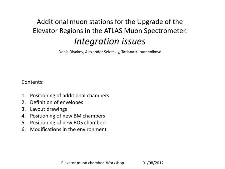
Additional muon stations for the Upgrade of the Elevator Regions in the ATLAS Muon Spectrometer . Integration issues. Denis Diyakov, Alexander Seletskiy, Tatiana Klioutchnikova. Contents: P ositioning of additional chambers Definition of envelopes Layout drawings

E N D
Additional muon stations for the Upgrade of the Elevator Regions in the ATLAS Muon Spectrometer. Integration issues Denis Diyakov, Alexander Seletskiy, Tatiana Klioutchnikova • Contents: • Positioning of additional chambers • Definition of envelopes • Layout drawings • Positioning of new BM chambers • Positioning of new BOS chambers • Modifications in the environment Elevator muon chamber Workshop 01/08/2012
Positioning of additional chambers Following the “Proposal for the Upgrade of the Elevator Regions in the ATLAS Barrel Muon Spectrometer” from Muon community Atlas Design Office has implemented studies of the environment in sector 13 and defined the envelopes in accordance with the available space and positions for the additional chambers. The layout drawings have been produced for sides A and C.
2. BM station enveloppe dimensions According to the muon community proposal the new BM station will consist of the newly developed 15mm drift tube chamber with thickness of 200mm with 2 mechanically integrated RPCs, each 50mm thick. Some 50mm will be needed additionally for services. Total thickness of the new BM station = 200mm + 2x50mm + 50mm = 350mm The space available for rotation of the BM station allows the installation of a chamber containing 78 tubes (1190mm large in Z dimension) Manipulations during the installation are schematically presented in the sketch
The length along X axis of the new BM station is defined by the space in its run position. It should fit between BMF stations in sectors 12 and 14. The envelope length is proposed to be 2600mm keeping nominal clearance of about 35mm with BMF edges (alignment protection plates). This envelope should include the chambers, rails with their supports, as well as a mechanism of rotation during the installation.
4. Positioning of new BM chambers Main requirements for the positioning are to maximize the coverage with muon stations and to keep access to inner detector, calorimeters ,inner layer of muon stations electronics and other parts. The initial proposal of muon community to put 2 small stations in line with other BMLs will make opening process during shutdown much longer and more complicated and will require removal of the new stations for the elevator access. Another proposal is shown in Fig.2 and consists of keeping one longer chamber inside the coverage angle as close as possible below the other BML stations: IP It will be enough to move the station along longitudinal rails towards IP to bring it to storage position that will allow necessary access in the region. Space envelope for on-chamber services( el. Boxes, alignment equipment…) – to be defined, waiting for information
5. Positioning of new BOS chambers side A and C Side A Side C Run position for MDT/RPC chambers can be optimized. For the detailed design of the transport frame and support brackets we need to know the final positioning of MDT/RPC ( absolute and relative)
6. Modifications in the environment • Modifications in the environment of sector 13 needed for the installation of the new BM station: • Take out handrails around the elevator area on floor and strut levels. • Remove both ladders on the side where the installation should be done. The access to the strut platform during the installation is possible on the opposite side. • Make modifications of the strut platform to enlarge opening in X for the passage of the new BM station. • Remove temporarilyventilation pipes ( cooling of muon electronics) on strut level
6. Modifications in the environment • Modifications in the environment of sector 13 needed for the run and storage positions of the new BM station: • Reinstall removed parts of the strut platform • Reinstall the ladders in modified position. Make apart of it above the strut platform removable to allow the BM movement to the storage position • Put back the handrails around elevator area at floor level. • At the strut level the handrails should be modified according to the BM run position. • Reinstall modified cooling pipes
6. Modifications in the environment • Modifications in the environment of sector 13 needed for the installation and run position of the new BOS chambers • Remove existing cable trays and put cables in the new cable tray installed below the floor • Modify the floor supports for the installation of the chamber • Remove the access stairs temporary during installation if needed New cable tray