Download
1 / 13
190 likes | 719 Views
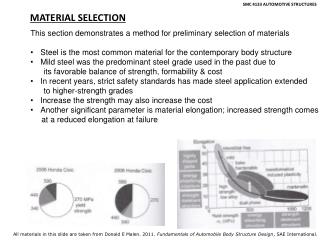
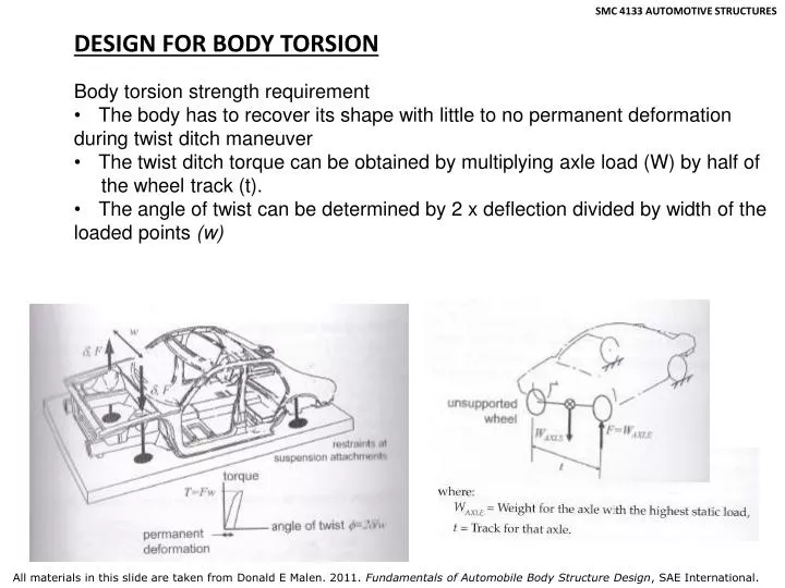
SMC 4133 AUTOMOTIVE STRUCTURES. DESIGN FOR BODY TORSION. Body torsion strength requirement The body has to recover its shape with little to no permanent deformation during twist ditch maneuver The twist ditch torque can be obtained by multiplying axle load (W) by half of

E N D
SMC 4133 AUTOMOTIVE STRUCTURES DESIGN FOR BODY TORSION • Body torsion strength requirement • The body has to recover its shape with little to no permanent deformation • during twist ditch maneuver • The twist ditch torque can be obtained by multiplying axle load (W) by half of • the wheel track (t). • The angle of twist can be determined by 2 x deflection divided by width of the • loaded points (w) All materials in this slide are taken from Donald E Malen. 2011. Fundamentals of Automobile Body Structure Design, SAE International.
SMC 4133 AUTOMOTIVE STRUCTURES DESIGN FOR BODY TORSION • Torsion stiffness requirement: • To ensure good handling properties • To ensure a solid structural feel and minimize relative deformations – • squeaks & rattles • As a vehicle turns a corner, it will roll and causes a weight transfer. It • then can affect steering characteristics • High body torsional stiffness is required to ensure good vehicle handling • Typical roll stiffness is 1000 Nm/deg while ride spring rate = 23.4 N/mm All materials in this slide are taken from Donald E Malen. 2011. Fundamentals of Automobile Body Structure Design, SAE International.
SMC 4133 AUTOMOTIVE STRUCTURES DESIGN FOR BODY TORSION • Let’s view the stiffness system as a series connection of springs • Keff/Kroll = 1.0 • Kbody = 10 Kroll • Kbody = 10000 Nm/degfor good • handling • For good solid structure feel: • Vehicle torsional frequency from 22-25 Hz • Torsional stiffness = 12000 Nm/deg • Torsion strength = 6250 Nm All materials in this slide are taken from Donald E Malen. 2011. Fundamentals of Automobile Body Structure Design, SAE International.
SMC 4133 AUTOMOTIVE STRUCTURES DESIGN FOR BODY TORSION • Load Path Analysis • To determine loads on individual structure elements • With these loads those elements can be designed • Let’s begin with a simple structure i.e. • a closed box. • The box is loaded by a twisting couple • at the front and rear corners • All panels are loaded All materials in this slide are taken from Donald E Malen. 2011. Fundamentals of Automobile Body Structure Design, SAE International.
SMC 4133 AUTOMOTIVE STRUCTURES DESIGN FOR BODY TORSION • - Edge loads & shear flows can be • calculated • AQ = T • A is a coefficient matrix • Q is an edge load matrix • T is an applied torque matrix • Shear flow, q = Q/L (N/m) All materials in this slide are taken from Donald E Malen. 2011. Fundamentals of Automobile Body Structure Design, SAE International.
SMC 4133 AUTOMOTIVE STRUCTURES DESIGN FOR BODY TORSION Example 1 Determine the edge loads for the torsion case All materials in this slide are taken from Donald E Malen. 2011. Fundamentals of Automobile Body Structure Design, SAE International.
SMC 4133 AUTOMOTIVE STRUCTURES DESIGN FOR BODY TORSION Example 2 All materials in this slide are taken from Donald E Malen. 2011. Fundamentals of Automobile Body Structure Design, SAE International.
SMC 4133 AUTOMOTIVE STRUCTURES DESIGN FOR BODY TORSION Example 2 Determine the edge loads for the given torsion load case All materials in this slide are taken from Donald E Malen. 2011. Fundamentals of Automobile Body Structure Design, SAE International.
SMC 4133 AUTOMOTIVE STRUCTURES DESIGN FOR BODY TORSION Analysis of body torsional stiffness: Closed box • Energy method will be used to predict • torsional stiffness by taking into account • panel dimensions, thicknesses and • material properties All materials in this slide are taken from Donald E Malen. 2011. Fundamentals of Automobile Body Structure Design, SAE International.
SMC 4133 AUTOMOTIVE STRUCTURES DESIGN FOR BODY TORSION Effective shear rigidity • to predict realistic torsional stiffness where • in reality the body panels differ considerably • from an ideal flat plate • Typically, the body panels are crown shape, • have holes, cut-outs and framework with • flexible joints All materials in this slide are taken from Donald E Malen. 2011. Fundamentals of Automobile Body Structure Design, SAE International.
SMC 4133 AUTOMOTIVE STRUCTURES DESIGN FOR BODY TORSION • Example 3 • Determine torsional stiffness of a box van based on: • Given shear rigidity • Effective shear rigidity: rear hatch opening • Data: w = 1400mm, h = 1250mm, L = 2000mm, G = 80000N/mm^2, t = 1mm • Solution: • K = (2x1400x1250)^2 x (1/(2x(21.9+35+31.3)) • = 6.95E+10 Nmm/rad = 1.22E+6 Nm/degree • b) Work done = Energy in the joints • ½ x F x delta = 4 x ½ x Kj x theta^2 • theta = delta/b, S = 4Kj/b^2, Gt = 4Kj /ab • Given Kj = 0.1E+8Nmm/rad • K = (2x1400x1250)^2 x (1/(21.9+35+35+31.3+31.3+76553)) • = 1.6E+8 Nmm/rad = 2807Nm/degree All materials in this slide are taken from Donald E Malen. 2011. Fundamentals of Automobile Body Structure Design, SAE International.
SMC 4133 AUTOMOTIVE STRUCTURES DESIGN FOR BODY TORSION Analysis of body torsional stiffness: Sedan Gt = (Q/delta) x (H/L) Delta is obtained from FEA All materials in this slide are taken from Donald E Malen. 2011. Fundamentals of Automobile Body Structure Design, SAE International.
SMC 4133 AUTOMOTIVE STRUCTURES DESIGN FOR BODY TORSION Example 4 From Example 2, determine the cabin torsional stiffness with side-frame. q = 2678/1250 = 2.1414N/mm q/T = 2.77E-7 mm^-2 Let Q/delta = 374.5 N/mm, Gt7-8 = 374.5x1250/2000 =234N/mm (side frame) A1=A5=1170000mm^2, A2=1103087mm^2, A3=1950000mm^2, A4=872067mm^2 A6=3120000mm^2, A7=A8=2312500mm^2 Gt 1-6 = 80000 N/mm Thus, K = 6.55E+ 8 Nmm/rad = 11491 Nm/degree All materials in this slide are taken from Donald E Malen. 2011. Fundamentals of Automobile Body Structure Design, SAE International.