Download
1 / 49
490 likes | 617 Views
STUK- independent Regulatory Body for nuclear and radiation safety in Finland and the use and role of TSO’s. VN/RA/01 Task 1&2 Workshop Hanoi, October 2012 Confidential Ilari Aro Ref. to Ilona Lindholm, Keijo Valtonen STUK. Nuclear power programme in Finland. Fennovoima Ltd

E N D
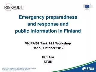
STUK- independent Regulatory Body for nuclear and radiation safety in Finland and the use and role of TSO’s VN/RA/01 Task 1&2 Workshop Hanoi, October 2012 Confidential Ilari Aro Ref. to Ilona Lindholm, Keijo Valtonen STUK
Nuclear power programme in Finland • Fennovoima Ltd • New utility, no operating reactors • DiP approved for FA1, Hanhikivi Site • Loviisa NPP (Fortum) • 2 operating units – VVERs • Interim Spent Fuel Storage at site • L/ILLW repository • Olkiluoto NPP (TVO) • 2 operating units - ABB BWRs • OL3 (EPR) under construction • DiP approved for OL4 • Interim Spent Fuel Storage at site • L/ILLW repository • Posiva “Onkalo” Photo: Fortum Photo: TVO
STUK - Radiation and Nuclear Safety Authority Mission: Protecting people, society, environment, and future generations from harmful effects of radiation
Regulatory Body • use of nuclear reactors • nuclear waste and materials • use of radiation • Research Centre • health effects of ionising and non-ionising radiation • natural radiation - occurrence and prevention • environmental research • radiation threats and preparedness for accidents • dosimetry and metrology • medical use of radiation • non-ionising radiation • Expert organisation • national preparedness for radiation accidents • information and advice to public and other authorities • contracted expert services • radiation measuring and calibration services Organisation Figures indicate staff number (356) at the end of 2011.
Main organizations involved in licensing and safety assessment in Finland Government Ministry Licenses STUK Safety assessment Statement on nuclear safety Main TSO: VTT Safety analysis
TypicalTSO’s in Finland for safetyanalysis and research • VTT – TechnicalResearch Centre of Finland • Branches for alltechnicalfields of society • For nuclear and wastesafetyabout 100 experts (altogetherabout 2000 staff) • Main TSO for STUK • Geological Institute and seismologicalinstitute for sitingstudies • Meteorologicalinstitute for meteorology and emergencyresponse • Universities (e.g. Helsinki, Aalto and Lappeenranta universities) e.g. radiochemistry, nuclearwaste, thermohydraulics and severeaccidentresearch
Review and Assessment by the Regulatory Body • Licensee is responsible to demonstrate safety and fulfilment of safety requirements (requirements are presented in the YVL guides) • STUK conducts independent review and assessment in licensing steps (before license is granted) and before modifications are implemented at the plants • Focus and scope of STUK’s review and assessment depends on the licensing phase • Safety assessment tools such as deterministic and probabilistic safety analyses are utilised in STUK’s review and assessment • STUK has established internal guidance for review work to ensure consistent review and assessment process and application of graded approach • Technical Support Organisations are utilised in specific areas (e.g. comparative accident and transient analyses), but STUK makes decisions on the safety case
DiD-levels, event categories and frequency of events belonging to each category Ilari Aro, 31 October 2010
Acceptance criteria for radioactive releases / max doses to general public • DBC 1, Normal operation • radiation dose limit 0,1 mSv / year for the entire site • DBC 2, Anticipated operational occurrences • radiation dose limit 0,1 mSv • DBC 3, Class 1 postulated accidents • radiation dose limit 1 mSv • DBC 4, Class 2 postulated accidents • radiation dose limit 5 mSv • DEC, Design extension conditions • radiation dose limit 20 mSv • SA, Severe accidents • release < 100 TBq Cs-137 equivalent • no acute health effects Ilari Aro, 31 October 2010
Acceptance criteria for fuel • DBC 1 , Normal operation • DBC 2 , Anticipated events • 95/95 confidence with respect DNB or dry-out, no (internal) fuel melting, nor damage due to pellet-cladding mechanical interaction. • DBC 3 “Class 1” postulated accidents • number of rods in heat transfer crisis < 1%, PCT < 650 °C, and extremely low probability of fuel damage by the mechanical interaction between fuel and cladding • DBC 4 ”Class 2" postulated accidents • the higher the frequency of a postulated accident, the smaller the number of damaged fuel rods. Number of damaged fuel rods < 10%. Max PCT < 1200 C. Limited enbritlement. Enthalpy limit 140 cal/g for failure (230 cal/g not be exceeded). Enthalpy limits are valid for fuel burnups up to 40 MWd/kgU. Limits for higher burnups shall be justified by experiments. No danger to long-term coolability • DEC, Design extension conditions • DEC A • Max PCT < 1200 C. Limited enbritlement. Enthalpy limit 140 cal/g for failure (230 cal/g not be exceeded). No danger to long-term coolability • DEC B, • Max PCT < 1200 C. Limited enbritlement. Enthalpy limit 140 cal/g for failure (230 cal/g not be exceeded). No danger to long-term coolability STUK
Analyses of plant behaviour: Examples of cases to be analysed • Examples of initiating events to be analysed are: DBC 2 • disturbance in the reactor power control or other disturbance, which causes a change in reactivity • disturbance in primary circuit flow, pressure control or water volume control • disturbance in steam pressure or steam flow • disturbance in feedwater flow or feedwater temperature DBC 3,4 • leaks from the primary circuit during power operation, change in operational state, refuelling and/or outage • leak from secondary circuit (PWR) • leak from primary to secondary circuit (PWR) STUK
Design Extension Conditions (DEC) • DEC A • includes conditions in which a common cause failure (CCF) in a safety system is assumed during anticipated operational occurrence (DBC 2) or class 1 accident (DBC 3), overall frequency of an event ~10-4 - 10-5 • as an example • ATWS • station black out • total loss of feed water • LOCA together with the complete loss of one emergency core cooling system • total loss of the CCWS • total loss of the RHR • loss of ultimate heat sink • loss of fuel pool cooling • realistic assumptions are applied for accident analysis • single failure is assume in safety systems • DEC B • includes complex sequences and rare external events • as an example • multiple stem generator tube rupture (~10) • extreme weather condition • large airplane crash • realistic assumptions are applied for accident analysis STUK
Analyses of plant behaviour: Examples of severe accidents • Severe accident analyses shall be used to study factors which affect containment integrity, leak tightness and the operability of containment systems. They could include i.e.: • total, long lasting loss of AC power • total loss of feedwater • leak of primary coolant without emergency cooling during power operation or a maintenance, refuelling or other outage • leak of primary coolant and blockage of coolant recirculation STUK
Analyses of releases and radiation doses : Examples of postulated accidents • Separate radiation dose analyses shall be made if the dose upper limit cannot be concluded from the results of other analyses. Some examples are: • Large leak of coolant from the primary circuit during power operation. A typical example of accidents during which radioactive substances are first released into the containment and gradually leak out. • Leak of reactor coolant outside the containment due to an instrument line rupture • Leak from steam generator primary to secondary side. The total rupture of one or multiple steam generator tubes shall be analyzed by assuming that also the safety valve of the steam generator has stuck open in a case it is expected to open. Also a leak larger than the one mentioned above shall be analyzed if estimated possible on the basis of the structure of the steam generator. • Leak out of the primary circuit during a maintenance, refuelling, or other outage. STUK
Analyses of releases and radiation doses : Examples of postulated accidents (continued) • Leak outside the containment in an unisolated steam line connecting to a steam generator in which, before the initiation of the accident, the largest primary to secondary circuit leak (PWR) allowable in the Technical Specifications has occurred. • Leak in a steam line outside the containment or in a reactor coolant purification line (BWR). • Damage outside the containment in a system containing radioactive gases. • Damage outside the containment in a system containing radioactive liquids. • Damage of a fuel assembly which has been removed from the reactor. • Dropping of a transfer or transport cask containing spent fuel during hoisting, in a situation where the cask is not tightly closed, or dropping of the fuel cask during transfer. • Dropping of a heavy object on top of stored fuel or an open reactor. • Severe accidents • Analyses shall be carried out for cases which on the basis of containment behaviour and conditions and the concentration of radioactive substances in the containment are estimated to cause the most extensive releases. STUK
Reliability of the analysis methods • Methods of analysis mean i.a. methods based on hand calculations, computer programs and the application of experimental data. The reliability of the analysis methods used shall be justified. A description of the analysis methods used shall be given, including their general principles as well as the physical models and numerical methods used. • The experimental correlations used in the calculations shall be justified by presenting the measurement data from which the correlations have been derived. If the correlation is commonly known and the measurement data are publicly available, a bibliographic reference is sufficient. • The analysis methods shall be adequately verified for the treatment of the events in question. Both numerical methods and physical models shall be verified. • Numerical methods shall be verified by adequate reference calculations. Physical models shall be verified by demonstrating their ability to depict suitable separate effects tests or integral tests for complete systems or nuclear power plant transients. In addition, comparison with other, earlier verified models may be utilised. • If sufficiently reliable calculation methods are not available, the analysis shall be justified by experiments. This requirement applies especially to most phenomena essentially relating to severe accident management, for example, the long term coolability of reactor core debris after a severe accident.
Performing safety analysis • Limiting transients or accident cases are selected from the point of view of fuel design criteria or pressure vessel design criteria or for containment analysis purposes. The purpose is to check that design values are according to the regulatory requirements, input data has been properly selected and that there are enough conservatism and design margin in design. Also the analysis models are checked by using comparison analyses with different analysis tools. • The ideal case is to use different calculation codes and models. In most cases this also takes place. In this respect, STUK has been quite successful. • VTT in Finland has the role of developing analysis tools or transform them into the Finnish conditions, test their validity and verification and also to perform safety analysis when needed. VTT validates the codes e.g. by performing some benchmark calculations against experiments or as international co-operation. • In Finland, originally, many computer codes used were of US design and it was necessary to apply them into the reactor systems that were different from the original purposes. For this reason, VTT was needed for this basic design and verification work. Currently, VTT has developed its own analysis tool system that is efficient in the safety analysis.
Performing safety analysis • Analysis tools are mainly provided by VTT or via VTT to STUK. STUK has also developed some computer codes by itself: e.g. for PSA and for radiation safety calculations. • If necessary, STUK requires from the licensee also the analysis tools and the input data used for its review in addition to the analysis reports and results. For the safety assessment purposes, different computer codes and models are mainly used. • Power companies typically use codes developed by the plant vendor e.g. ABB computer codes for BWR or they have supported the development of own codes as Fortum/VTT codes for VVER. STUK mainly uses codes developed by VTT or which have been received through international co-operation e.g. with US NRC.
What to assess - plant level Nuclearsafetyanalysis • Plantfunctional design (anticipatedtransients, design basisaccidents, design extentionconditions, severeaccidents, PSA, radioactivereleases, environmentaleffects) • Siteevaluation and environmentalaspects Plant design - systemanalysis • system design features and description - compliancewith design criteria • safetyclassification, QA/QC requirements, regulatorycontrol • systemfailureanalysis - redundancy, diversity, separation, interactionwithothersystems, riskassessment • systemoperation - functionalrequirements; operationduringdifferentplantstatesincludingaccidents • environmentalconditions & classification • operationallimits and conditions, surveillance and testing
Criteria for safety assessment (plant level) • General design criteria • basis for safetyassessmentreviewreport • YVL guides • YVL 1.0 Safetycriteria for design of nuclearpowerplants • YVL 2.2 Transient and accidentanalyses for justification of technicalsolutions at nuclearpowerplants • YVL 2.8 Probabilisticsafetyanalyses (PSA) • YVL 6.2 Fuel design limits and general design criteria • YVL 7.1 Limitation of publicexposure in the environment of and limitation of radioactivereleasesfromnuclearpowerplants • YVL guide 2.0 givescriteria for the design of safetysystems • YVL 2.1 coversafetyclassification • YVL 2.7 coverfailurecriteria • YVL 1.4 cover QM • YVL 2.5 coverpre-operational and start-uptesting of NPP • YVL guidesystemprovidedetailedcriteria for structures, systems and components
System design requirements • Safety classification based on PSA insights • N+2 failure criterion for systems that deal with design basis events; besides redundancy, also adequate diversity and segregation • Proven technology • properly evaluated operational experience • experimental demonstration & analysis (novelties, such as “passive” systems) • Adequate demonstration of performance and safety margins on the basis of deterministic studies and PSA
Design basis for containment 1) Large break LOCA • adequate capacity to carry pressure loads and to limit radioactive releases must be shown in conditions expected after a LB LOCA containment • this gives a sound basis to manage also severe accidents 2) Severe accidents • all foreseeable loads threatening the containment integrity in connection with a severe core damage must be identified, and necessary protection (prevention or mitigation) must be provided against each load • in Olkiluoto 3, pressure caused by hydrogen burn is the limiting designevent for containment 3) External events • potential external events must be identified and protected against
Features required to mitigate severe accidents • Severe accident management strategy is mandated in containment design • high pressure failure of reactor vessel prevented by dedicated depressurization system • hydrogen management with autocatalytic recombiners to prevent detonation • low pressure melt arrested in a core catcher, with passive long-term cooling • containment integrity against dynamic loads • containment pressure management in long term • containment leak tightness criteria from release limits • AC power supply systems and I&C systems dedicated to support severe accident management are required • For systems dedicated for protection against severe accidents, single failure criterion applies
Protection against external threats After September 11, 2001: political and public will was expressed to improve protection against terrorist actions • Reconsideration of aircraft crash design basis • consider large passenger and military aircrafts • no immediate release of significant amount of radioactive substances • initiation and maintenance of key safety functions in spite of the direct consequences of the event (penetration of structures by impacting parts, vibration, explosion, fire) • Microwave and biologic weapon consideration
Integral severe accident analyses Containment performance Core and primary system MELCOR CONTAIN SCDAP/RELAP5 Pressure vessel integrity in severe accidents PASULA Computer programs for safety analysis in VTT in Finland ENDF/B, JEF NJOY CASMO libraries Nuclear Data APROS simulation environment RELAP5/Mod3 Thermal hydraulics Plant analyzer Training simulator Thermal hydraulics Assembly wise group constants CASMO 4 SIMULATE rectangular HEXBU-3D hexagonal Severe accidents Reactivities, power and burnup ENIGMA, FRAPCON, SCANAIR, FRAPTRAN FRAPTRAN-GENFLO Steady state and transient fuel behaviour TRAB-3D BWR HEXTRAN VVER Transient and accident analyses with 3D core model, complete circuit models
Example on coupling of safety codes used in accident analysis
PSA tool in use in STUK • FinPSA is a comprehensive risk and reliability analysis tool intended for full scope PSA/PRA modeling. The tool has been developed and maintained since 1988 by Radiation and Nuclear Safety Authority of Finland (STUK). The tool is designed to support the main activities related to PSA/PRA by easy model creation, efficient and versatile analysis, good traceability, flexible reporting and information exchange capabilities. All these features make your work comfortable in living PSA, plant assessment and operational modifications. From the beginning of 2012, STUK and VTT (Technical Research Centre of Finland) have initiated a project to develop the tool ahead and to train new FinPSA experts.
TSO Support for Olkiluoto 3 Review Criteria for TSO’s; • Competent organisation to carry out EPR analysis • Independent from the licensee • Codes independent from the licensee’s codes • Adequately validated codes for EPR Main organisations used as TSO’s were • Technical Research Centre of Finland (VTT) • Institute for Safety and Reliability (ISar) Main computer codes used by TSO’s • TRAB3D/SMABRE (VTT) • APROS (VTT) • MELCOR (VTT) • ATHLET (ISar)
TSO Support for Olkiluoto 3 Review Main Finnish organisations used were Technical Research Centre of Finland (VTT) and Lappeenranta Technical University (LTU) VTT: • Transient analyses with the TRAB3D/SMABRE code • Design Basis Accident analyses with the APROS code • Independent comparative analyses of primary circuit behaviour during accident situations • Small break LOCA • Steam Generator Tube Rupture • Large break LOCA
Tools for SevereAccidentAssessment • Integralsevereaccidentanalysistools • Used for assessment of progression of wholeaccidentscenario • Good for assessment of overallperformance of ESF • Applicablealso for PRA level 2 studies • Detailed, separateeffectssevereaccidentcodes • State-of-the-artmodels • Used for in-depthstudies of safetycritical SA phenomena • Generallyrelated to phenomenathatcannotbemodelled/solvedwith the methodologyused in integralsystemsanalysiscodes • Experiments • Lastresort to supportorvalidateanalyticalresults • Equipmentsurvivabilitystudies
Analytical tools • Integral system codes obtained from abroad • Detailed, separate effects SA codes obtained from abroad or developed at VTT • Experiments: • Participation in major international experimental research programmes • Small-scale experiments/testing also in-house
Integral Severe Accident Analysis Tools at VTT • MELCOR (version 1.8.6 and 2.1) for integral plant analysis, source term, developed in Sandia National Lab’s for USNRC • Main severe accident analysis tool since 1990 at VTT • Validation: Sandia’s validation and QA • PCCS condenser application tested against: • Concrete erosion model validated against various OECD/MCCI experiments • Plant models for Loviisa 1&2, Olkiluoto 1&2, Olkiluoto 3 • ASTEC Integral plant analysis, source term, developed by IRSN (France)/GRS (Germany) • Participation in ASTEC users group for validation efforts since 2011 • Only RPV lower head melt pool studies performed so far • Applications of fission product source term models under way • Long-term goal to build full plant inputs for Finnish NPPs
SeparateEffectsSevereAccidentAnalysisTools at VTT (1/4) • PASULA code suite for detailed mechanical analyses of structures • Creep rupture of lower head • Lower head penetration integrity • Ex-vessel cooling of lower head • Validation against several Sandia’s LHF and OLHF tests • Applied for Loviisa 1 & 2, Olkiluoto1 & 2 and SWR-1000 reactors
SeparateeffectsSevereAccidentAnalysisTools at VTT (2/4) • CORQUENCH for concrete erosion, melt pool coolability, developed at Argonne National Lab for USNRC • Code tested at VTT against various CCI-tests and COMET-tests • FLUENT (CFD code) for hydrogen mixing and deflagration combustion, commercial UK code • Tested at VTT against THAI-experiments for mixing • Tested at VTT against FLAME tests for flame speed and acceleration • Applied for Olkiluoto 1,2,3 and Hungarian Paks (VVER 440) • TONUS for hydrogen detonation, developed at CEA, France • Tested at VTT against ENACEFF tests for flame acceleration • Tested at VTT against FLAME experiments for detonation • DET3D for hydrogen detonation, developed at FZK, Germany • Interface with ABAQUS structural analysis code
SeparateeffectsSevereAccidentAnalysisTools at VTT (3/4) • TEXAS-V for steam explosions, developed at UW, USA • Validated at VTT against KROTOS experiments KS-1 and KS-2 Applied for Olkiluoto 1 & 2 • MC3D V3.5 for steam explosions, developed at IRSN, France • Validation at VTT ongoing against KROTOS and TROI tests • Applied for Olkiluoto 1&2 • MEWA for corium particle bed coolability, developed at IKE Stuttgart • Validation at VTT against own STYX and COOLOCE experiments • Applied for Olkiluoto 1 & 2 • CONTAIN 2.0 for containment T/H and source term analyses, developed at Sandia National Lab for USNRC • Validation at VTT against Fortum’s VICTORIA tests, HDR tests • Applied for Loviisa 1 & 2
SeparateeffectsSevereAccidentAnalysisTools at VTT (4/4) • CHEMPOOL for calculation of pH in containment pools, developed at VTT • Validated against a matrix of titration experiments • QA’ed for application in safety related work to US • Used for supporting design calculation for design of pH control system of OL1/OL2 • Applied also for Olkiluoto 3 and ESBWR (GEH) • RADTRAD for dose calculations for DBA cases (NRC Regulatory Guide 1.183); developed for USNRC • Applied for Ringhals 2 (Westinghouse PWR)
Application example: Olkiluoto unit 1 and 2 BWR 860 MW • RPV failuremode • Effects of recriticality • Hydrogen • Coredebriscoolability • Steamexplosions • pH control • Elastomersurvivability • Paintedwallstructuredecontamination
OLKILUOTO 1 and 2 BWR 860 MW • Containment inerted with nitrogen in-containmenthydrogencombustionrisklow • Hydrogengeneration contributes to containmentpressurization and H2 leak to RB • Recriticality • RPV is assumed to fail debris coolability and stabilization in the LowerDrywellcrucial • Flooding of LowerDrywellprior to PressureVesselfailure particlebed coolability is an issue • Ex-vesselsteamexplosions • Containmentpool pH conrol
RPV lower head penetrations MCP penetration Instrumenttubepenetration Controlrodpenetration
Penetration failure • Penetration weld fails by loss of strength in about 40 s after contact with melt • Instrument tube inside nozzle tube (”blue tube”) can fall downward and open a flow path • Uncertainties: • Falling tube becomes stucked at lower elevation • Refreezing of melt blockage in discharge channel • Control rod penetration would fail 5.5 hours after melt arrival • RCP opening would fail 5.2 hours after arrival of melt Liquid corium, T=2550 K Weld RPV wall Instrument tube
Creep rupture of lower head • Ifcorium is notable to dischargethrough a failedpenetration • Heatfluxesfrom the meltpool to the RPV wallobtainedfrom MELCOR calculation • Creepruptureoccursnear the interface of metallic and oxidic meltlayer at 5.5 hoursaftermeltarrival • Practically no difference in timingbetween RPV wallcreeprupture, controlrodtubefailure and RCP openingfailure • But, the initialholeareasmaydiffer