Download
1 / 37
380 likes | 705 Views
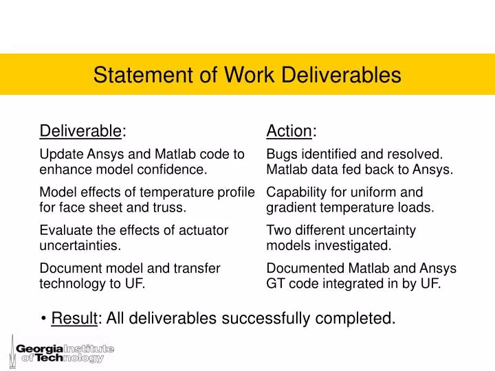
Statement of Work Deliverables. Result : All deliverables successfully completed. Statement of Work Deliverables Update of Previous Work – Correction of Matched CTE Cases Ansys Verification of Matlab Results Matlab Actuator Displacements Fed Back to Ansys (closed the loop)

E N D
Statement of Work Deliverables • Result: All deliverables successfully completed.
Statement of Work Deliverables Update of Previous Work – Correction of Matched CTE Cases Ansys Verification of Matlab Results Matlab Actuator Displacements Fed Back to Ansys (closed the loop) Thermal Aberration Reproduction vs. Correction Actuator Glitch Evaluation Random Glitch Discrete Glitch Actuator Forces Evaluation Concluding Remarks Overview
Parameters Facesheet: Diameter (tip to tip) 2m F-number 1.5 Thickness m Modulus of Elasticity 95 GPa Poisson’s ratio 0.35 CTE 13E-6 /°C Substrate data: Beam diameter 1.16 mm Modulus of elasticity 68.3 Gpa Poisson’s ratio 0.33 CTE 0 /°C Actuator stiffness 2N/m Thermal loads: 1) 10°C uniform 2) 1°C/m gradient Actuators cases: 1) 15 2) 159 3) 1563
Problem: Similar displacements for matched and unmatched CTEs of the facesheet and truss. Update of Previous Work – Correction of Matched CTE Cases 10°C uniform load – 159 actuators Mismatched CTEs Matched CTEs(incorrect) Facesheet only • Solution: Bug fixed in Ansys code so correct CTEs assigned in the matched case.
Problem: Similar displacements for matched and unmatched CTEs of the facesheet and truss. Update of Previous Work – Correction of Matched CTE Cases 10°C uniform load – 159 actuators Mismatched CTEs Matched CTEs(incorrect) Facesheet only • Solution: Bug fixed in Ansys code so correct CTEs assigned in the matched case.
Correction of Matched CTE Cases - 10ºC Uniform, 159 Actuators Matched CTE case is now similar to the facesheet only case. PreviousFacesheet only Previous Matched CTEs UpdatedMatched CTEs
Correction of Matched CTE Cases - 1ºC/m Gradient, 159 Actuators Matched CTE case is now similar to the facesheet only case. PreviousFacesheet only Previous Matched CTEs UpdatedMatched CTEs
Previously, Ansys provided influence coefficients and the response to thermal loads. These were imported into Matlab to calculate actuator displacements to reproduce the aberration. Currently, the Matlab-calculated actuator displacements are fed back into Ansys to either: Correct the thermally loaded system. Reproduce the thermal aberrations by actuation from an initially unloaded system (similar to previous Matlab work). Results: Correct and Reproduce yield similar results. ANSYS Verification of Matlab Results
Summary: Reproduction vs. Correction • Results: The correction is produced with essentially the same accuracy as the reproduction.
Ansys Plots: Reproduction vs. Correction • Reproduction vs. Correction Plots: • 15 actuators, 10ºC Uniform • 15 actuators, 1ºC/m X-Gradient • 159 actuators, 10ºC Uniform • 159 actuators, 1ºC/m X-Gradient • 1563 actuators, 10ºC Uniform • 1563 actuators, 1ºC/m X-Gradient
10ºC Uniform, 15 Actuators Correction Reproduction
1ºC/m X-Gradient, 15 Actuators Correction Reproduction
10ºC Uniform, 159 Actuators Correction Reproduction
1ºC/m X-Gradient, 159 Actuators Correction Reproduction
10ºC Uniform, 1563 Actuators Correction Reproduction
1ºC/m X-Gradient, 1563 Actuators Correction Reproduction
Actuator Glitch Three cases of actuator glitch are compared: No Glitch – actuators have infinite resolution. Discrete Glitch – actuator displacements are multiples of 50 nm. Random Glitch – a random glitch between +/- 50 nm is added to each actuator displacement. Results: The RMS errors are not sensitive to smallglitches. (Small is relative to maximum actuator strokes).
Glitch Summary • Result: Glitch Additional RMS Error % Glitch/Maximum Actuator Stroke %.
Ansys Plots: Actuator Glitch • No Glitch vs. Discrete Glitch vs. Random Glitch: • 15 actuators, 10ºC Uniform • 159 actuators, 10ºC Uniform • 1563 actuators, 10ºC Uniform • 15 actuators, 1ºC/m X-Gradient • 159 actuators, 1ºC/m X-Gradient • 1563 actuators, 1ºC/m X-Gradient
10ºC Uniform, 15 Actuators No Glitch Random Glitch Discrete Glitch
10ºC Uniform, 159 Actuators No Glitch Random Glitch Discrete Glitch
10ºC Uniform, 1563 Actuators No Glitch Random Glitch Discrete Glitch
1ºC/m X-Gradient, 15 Actuators No Glitch Random Glitch Discrete Glitch
1ºC/m X-Gradient, 159 Actuators No Glitch Random Glitch Discrete Glitch
1ºC/m X-Gradient, 1563 Actuators No Glitch Random Glitch Discrete Glitch
Force Evaluation Increasing numbers of actuators, increases required actuator forces. 15 actuators case met force specifications (< 0.1N) for both 10ºC Uniform and 1ºC/m X-Gradient loads. 159 and 1563 actuators cases exceed force specifications for both loadings. (Note: will add 45 and 93 actuator cases.) Actuator Forces
Ansys Plots: Actuator Forces • Force Plots • 15 actuators, 10ºC Uniform • 45 actuators, 10°C Uniform • 93 actuators, 10°C Uniform • 159 actuators, 10ºC Uniform • 1563 actuators, 10ºC Uniform • 15 actuators, 1ºC/m X-Gradient • 45 actuators, 1°C/m X-Gradient • 93 actuators, 1°C/m X-Gradient • 159 actuators, 1ºC/m X-Gradient • 1563 actuators, 1ºC/m X-Gradient
10ºC Uniform, 15 Actuators actuator forces aberration • Maximum actuator force within limit (< 0.1N).
10ºC Uniform, 45 Actuators actuator forces aberration • Maximum actuator force is exceeded (> 0.1N).
10ºC Uniform, 93 Actuators actuator forces aberration • Maximum actuator force is exceeded (> 0.1N).
10ºC Uniform, 159 Actuators actuator forces aberration • Maximum actuator force is exceeded (> 0.1N)
10ºC Uniform, 1563 Actuators Maximum actuator force is exceeded (> 0.1N) aberration actuator forces
1ºC/m X-Gradient, 15 Actuators Maximum actuator force is within limit (< 0.1N). actuator forces aberration
1ºC/m X-Gradient, 45 Actuators actuator forces aberration • Maximum actuator force is exceeded (> 0.1N).
1ºC/m X-Gradient, 93 Actuators actuator forces aberration • Maximum actuator force is exceeded (> 0.1N).
1ºC/m X-Gradient, 159 Actuators Maximum actuator force is exceeded (> 0.1N) actuator forces aberration
Only the 15 actuator case satisfied all specified criteria RMS errors for the two thermal loads were low, less than 1%. Maximum force levels required only 25% of the holding force. Maximum stroke was about 50% of maximum. Large P2V amplitudes corrected (1419 m and 254 m). Increasing actuators increased actuator forces to unacceptable levels. Concluding Remarks