Download
1 / 25
250 likes | 253 Views
Assemble Exploded Model GUI Familiarity Level Required: Lower Estimated Time Required: 30 minutes. MSC.ADAMS 2005 r2. Topics Covered. In this tutorial you will learn how to:. Create Marker Create Link Create Marker Create Revolute joint between 2 Bodies and 2 Locations

E N D
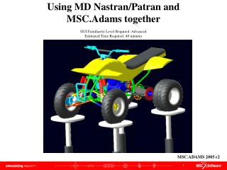
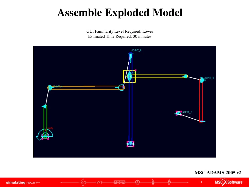
Assemble Exploded ModelGUI Familiarity Level Required: Lower Estimated Time Required: 30 minutes MSC.ADAMS 2005 r2
Topics Covered In this tutorial you will learn how to: • Create Marker • Create Link • Create Marker • Create Revolute joint between 2 Bodies and 2 Locations • Create Spherical joint between 2 Bodies and 2 Locations • Create Hooke joint between 2 Bodies and 2 Locations • Create Cylindrical joint between 2 Bodies and 2 Locations • Perform initial conditions solution If you have any difficulties, import the “assemble_exploded_model_shortcut_1.cmd” file and proceed from pg 16 If you have any difficulties, import the “assemble_exploded_model_shortcut_2.cmd” file and proceed from pg 19 If you have any difficulties, import the “assemble_exploded_model_complete.cmd” file and proceed from pg 23
Assemble Exploded Model This tutorial shows how you can build a model in an exploded or unassembled form and automatically have it assemble before simulation. This can be useful if your model is complicated and has many small and closely connected parts.
What You Should Accomplish When you complete this tutorial you will have an exploded model that assembles and then runs a simulation.
Getting Started Getting Started: a. Under the heading "How would you like to proceed", select the Create a new model radio button. b. Choose a Location to save your files c. Set Model Name as assemble_exploded_model d. Verify the Gravity text field is set to Earth Normal (-Global Y). e. Verify that the Units text field is set to MKS - m,kg,N,s,deg. f. Select OK. a b c d e f
Create Marker • Click on the View menu, select Coordinate Window • Select Marker tool from Rigid Body tool stack • Click (0, -0.5, 0) b a c
Create Markers Create markers at the following locations:
Create Link • Select Link tool from Rigid Body tool stack • Turn on the Width check box, enter (20.0cm) in the text field below • Turn on the Depth check box, enter (5.0cm) in the text field below • Click ground.MARKER_1 • Click ground.MARKER_2 a e b c d
Create Links • Create Links between: • ground.Marker_3 and ground.marker_4 • ground.Marker_5 and ground.marker_6 • ground.Marker_8 and ground.marker_9 • ground.Marker_10 and ground.marker_11 c a b d
Create Polyline • Select Polyline tool from Rigid Body tool stack • Select On Ground from pull down arrow • Click (-0.2, 0.4, 0.0) • Click (0.2, 0.4, 0.0) • Click (0.2, -0.65, 0.0) • Click (-0.2, -0.65, 0.0) • Click (-0.2, 0.4, 0.0) • Right-click to close b a c d g e f
Create Polyline • Create Polyline: • (5.55, -0.85, 0.0)(5.95, -0.85, 0.0)(5.95, -1.15, 0.0)(5.55, -1.15, 0.0)(5.55, -0.85, 0.0) • (8.85, 0.95, 0.0)(9.15, 0.95, 0.0)(9.15, 1.15, 0.0)(8.85, 1.15, 0.0)(8.85, 0.95, 0.0) b a
Create Box • Select Box from Rigid Body tool stack • Select Add to Part from Box pull down arrow • Turn on Length checkbox, enter (80.0cm)in the text field below • Turn on Height checkbox, enter (80.0cm) in the text field below • Turn on Depth checkbox, enter (20.0cm) in the text field below • Click PART_5 • Click (5.25, 3.1, 0) a f g b c d e
Modify Box Location • Right-click on box, select Marker: MARKER_24 Modify • Enter 5.25, 3.1, -0.1 in Location text field • Click OK b a c
Add Revolute Joint • Select Revolute joint from Joint stack • Select 1 Location from Construction pull down menu • Click on ground.MARKER_1 a b c
Create Revolute Joint • Create a revolute joint at ground.MARKER_5 a
Create 2 Body – 2 Location Revolute Joint • Click Revolute joint • Select 2 Bod-2 Loc from Construction pull down menu • Click PART_6 ground marker 11 marker 12 a b c
Add Rotational Motion • Click Rotational Motion from Motion Driver tool stack • Enter (360d) in Speed text field • Click JOINT_1 a b c
Create 2 Body – 2 Location Spherical Joint • Select Spherical Joint from Joint tool stack • Select 2 Bod-2 Loc from Construction pull down menu • Click PART_2 PART_3 ground.MARKER_2 ground.MARKER_3 • Create a second 2 Bod – 2 Loc spherical joint: • PART_5 PART_6 ground.MARKER_9 ground.MARKER_10 d c a b
Create 2 Body – 2 Location Hooke Joint • Select Hooke Joint from Joint tool stack • Select 2 Bod-2 Loc from Construction pull down menu • Click PART_3 PART_4 ground.MARKER_4 ground.MARKER_6 cm (PART_3) MARKER_17.X a c b
Create 2 Body – 2 Location Cylindrical Joint • Select Cylindrical Joint from joint tool stack • Select 2 Bod-2 Loc from Construction pull down menu • Click PART_4 PART_5 ground.MARKER_7 ground.MARKER_8 cm (PART_4) MARKER_5 a b c
Verify Verify your model NOTE: ADAMS/Solver will display errors because the distance between the two parts is too far for a joint to exist.
Model This is what your screen should look like when your model is complete
Run Simulation • Click Simulation tool • Click button • Click Perform initial conditions solution tool • Select Step Size from pull down arrow, enter 0.01 • Click Play e a d c b
Topics Covered In this tutorial you will learn how to: • Create Marker • Create Link • Create Marker • Create Revolute joint between 2 Bodies and 2 Locations • Create Spherical joint between 2 Bodies and 2 Locations • Create Hooke joint between 2 Bodies and 2 Locations • Create Cylindrical joint between 2 Bodies and 2 Locations • Perform initial conditions solution
Best Practices • Make sure the units are correctly set. • Make sure the joints is in the correctdirection. • Check dimensions of your parts to make sure they are correct. • Check orientation of the parts and joints to make sure it is correct. • Make sure your model verification is successful • Make sure the measures are set properly. • Make sure the plot is displaying the correct set of results.