Download
1 / 13
130 likes | 221 Views
The JLab IR/UV FEL Driver. D. Douglas for the JLab FEL anarcho-syndicalist commune. ERL Configuration & Performance. E~80-135 MeV I~10 mA (135 pC x 75 MHz) e N transverse ~ 5-10 mm- mrad (charge dependent) e N tlongitudinal ~ 50-100 keV-psec (charge dependent).

E N D
The JLab IR/UV FEL Driver D. Douglas for the JLab FEL anarcho-syndicalist commune
ERL Configuration & Performance E~80-135 MeV I~10 mA (135 pC x 75 MHz) eNtransverse ~ 5-10 mm-mrad (charge dependent) eNtlongitudinal ~ 50-100 keV-psec (charge dependent) Flexible large-acceptance transport system - transverse and longitudinal matching * variable spot size, bunch length, dp/p - phase-space exchange (IR side)
Key Features • DC photocathode gun • High brightness CW beam • SRF ERL system architecture • High power/high current • Large acceptance • optimized for momentum acceptance (FEL exhaust beam) • physical and dynamic (transverse&longitudinal) acceptance fairly large • 3” pipe in straights, ~1’ at high dispersion points • Good aberration control • UV bypass has “natural” location for detector • “wiggler pit” (photos from J. Boyce/A. Kelleher)
Practical Consequences • Very bright, extremely high power e- beam • Operationally flexible • => can run as NP testbed as well as FEL driver • e.g. rework longitudinal match to produce small momentum spread rather than short bunch and thus produce moderately small spot size and small momentum spread • At 60 pC (UV “native” mode) • sdp/p ~ 0.025% • sx,y~ 0.05 mm
Requirements/Issues for DarkLight • Requirements • Service gas jet target • Small spot size (target aperture constraint) • good beam stability • low background • Accommodate detector • Use UV wiggler pit (?) • High current • Energy recovery • Large spatial/energy acceptance after target/loss management • Issues • Aperture limits – can we fit beam through target? • Beam stability – is the beam stable enough to satisfy user/avoid scraping? • Halo – are backgrounds low enough? Do we burn things up? • Acceptance – can we recover beam with low enough losses?
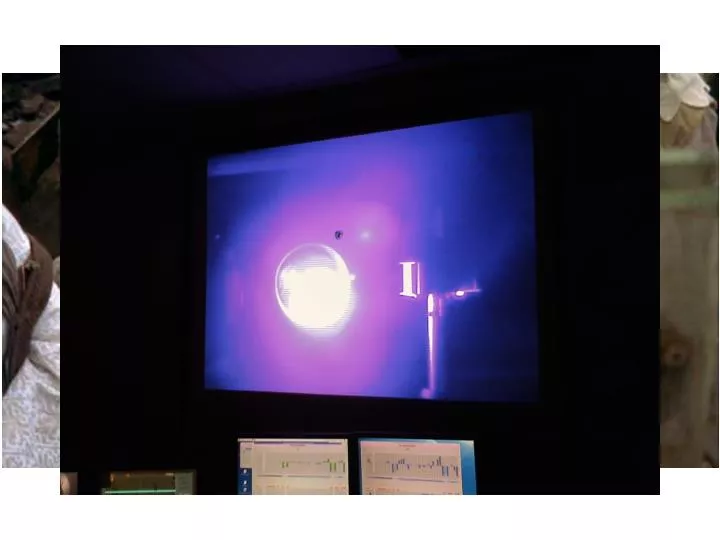
UV Operational Beam Courtesy C. Tennant
Beam Stability • Machine performance adequate for FEL operation without stabilization • Energy constant to ~few 0.01% or better short term (low jitter), only stable to few 0.1% over 10s of minutes • Position stable to ~several 10s of microns or better short term; may drift by ~100 micron over 10s of minutes • FEL user “runs” are short & machine tune-up reliably recovers initial setpoints; extended luminosity runs => better stability… • May need to provide low-bandwidth feedback to improve energy & position stability at target • Transfer standard CEBAF tools (need stability specs)
Acceptance • Machine usually optimized for FEL operation • “large acceptance” primarily devoted to handling large momentum spread • Impact of target on e- beam emittance is primary concern • Are electrons pushed out of accelerator acceptance? • Tail/halo formation (especially longitudinal; hard to handle w/o energy compression)? (Need to evaluate effect of target on beam) x’,y’ dp/p x,y t
Guesstimates • Checked large-amplitude behavior during system design – nonpathological • Momentum Acceptance quite large (assuming energy compression; smaller if on crest/in trough) • Physical acceptance ~3” full aperture • 0.0375 m amplitude acceptance at max. beam envelope (~50 m) • emax ~ (0.0375 m)2/50 m ~ 30 mm-mradgeometric ~6000 mm-mradnormalized (@ 100 MeV) (Need to repeat analysis after beam/target interaction is characterized)
“Real beams do not occur in distributions named after dead European mathematicians” – P. O’Shea Images courtesy P. Evtushenko
“core” vs. “edge” vs. “halo” • Beam is extremelynonuniform • In some places the transverse distribution looks like 2 or 3 superposed gaussians in one or both directions • In dispersed locations, the beam shows structure (filamentation) that appears to evolve through the system • We are forced to match “edge” of beam – the place the distributions all seem to tail off • Tried to match “core”, but which core do you match? • Hard to pick “which core is which” at different places or focusing settings • Core emittance smaller (~5-8 mm-mrad) but results inconsistent • Get shorter bunch, but raw detector signal is lower, implying you’re seeing only a fraction of the charge [hence, “match dependence of bunch length”] • Lasing not as good as when edges matched (longer bunch but more charge participates) • Picking a core to match causes mismatch in the others and in the halo, which gets very bad… (scraping)
Halo – when seeking the Grail (beam brightness), its “the violence inherent in the system…” • Halo = the large-amplitude “low”-intensity stuff you can’t use that scrapes off, messes up data, activates components, and burns things up • Example: 10 mA CW 1 mA loss tolerance => 10-4 relative loss upper limit • “the” major high-power ERL operational constraint • Beam loss, background radiation, activation, component damage… • Higher powers => worse halo effects • Comes from many sources, including drive laser, cathode, gun, beam formation processes, Satan, SRF cavities… • We see (and to some extent, manage) halo effects all the time • Halo components “mismatched” from core beam, can usually be managed with tuning knobs that don’t affect core beam too much • “magic” quads • octupoles • Have (historically) run high-duty factor (60 Hz) beam through small aperture (“halo monitor”) without evident loss • Significant concern in this situation • Small target aperture • Detector background (Need to characterize halo (next talk…), establish tolerance & demonstrate control with small aperture)
Conclusions, Status, To-Do Lists • Can support detector (UV side of machine) • Can appropriately configure beam for DarkLight target • need to spec detailed beam properties (optimum spot size, momentum spread) & generate machine tunings • Need to establish impact of target on beam & generate recovery tuning • review spatial acceptance, evaluate recovery matching (transverse & longitudinal) • Need to establish stability specs • May need low-bandwidth stabilization (a la CEBAF) • Halo management • characterize halo • demonstrate control through small aperture