Download
1 / 3

E N D
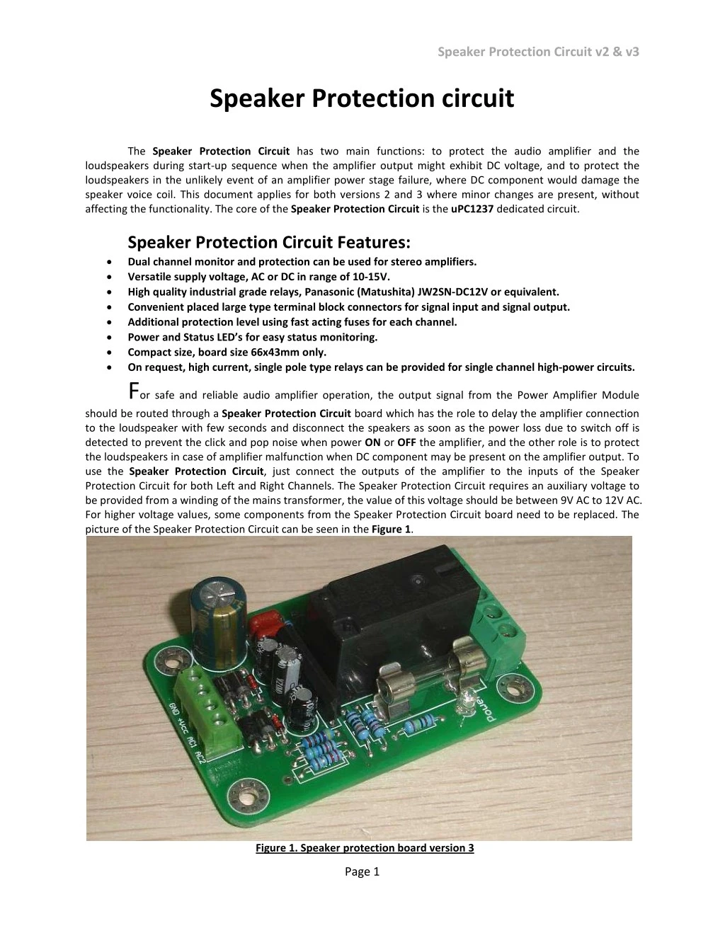
Speaker Protection Circuit v2 & v3 Speaker Protection circuit The Speaker Protection Circuit has two main functions: to protect the audio amplifier and the loudspeakers during start-up sequence when the amplifier output might exhibit DC voltage, and to protect the loudspeakers in the unlikely event of an amplifier power stage failure, where DC component would damage the speaker voice coil. This document applies for both versions 2 and 3 where minor changes are present, without affecting the functionality. The core of the Speaker Protection Circuit is the uPC1237 dedicated circuit. Speaker Protection Circuit Features: • Dual channel monitor and protection can be used for stereo amplifiers. • Versatile supply voltage, AC or DC in range of 10-15V. • High quality industrial grade relays, Panasonic (Matushita) JW2SN-DC12V or equivalent. • Convenient placed large type terminal block connectors for signal input and signal output. • Additional protection level using fast acting fuses for each channel. • Power and Status LED’s for easy status monitoring. • Compact size, board size 66x43mm only. • On request, high current, single pole type relays can be provided for single channel high-power circuits. For safe and reliable audio amplifier operation, the output signal from the Power Amplifier Module should be routed through a Speaker Protection Circuit board which has the role to delay the amplifier connection to the loudspeaker with few seconds and disconnect the speakers as soon as the power loss due to switch off is detected to prevent the click and pop noise when power ON or OFF the amplifier, and the other role is to protect the loudspeakers in case of amplifier malfunction when DC component may be present on the amplifier output. To use the Speaker Protection Circuit, just connect the outputs of the amplifier to the inputs of the Speaker Protection Circuit for both Left and Right Channels. The Speaker Protection Circuit requires an auxiliary voltage to be provided from a winding of the mains transformer, the value of this voltage should be between 9V AC to 12V AC. For higher voltage values, some components from the Speaker Protection Circuit board need to be replaced. The picture of the Speaker Protection Circuit can be seen in the Figure 1. Figure 1. Speaker protection board version 3 Page 1
Speaker Protection Circuit v2 & v3 Description: The amplifier outputs are routed to the Speaker Protection Circuit board at the connector J1, pin 2 for left channel and pin 4 for Right channel. The ground of the amplifier should be connected at the Speaker Protection Circuit GND at the same connector, pin 3. The outputs to the speakers are connected to pin 1 for left channel and pin 5 for right channel. Same GND pin 3 is used, as this pin carry no current at all, is used just for reference, it can be connected at the amplifier start GND without disconnecting the Ground path of the amplifier. The Speaker Protection Circuit can be powered with AC voltage in range of 8 to 12V AC, 50 or 60Hz and requires about 40mA for proper operation. This is a very small current which can be obtained from an auxiliary winding of any transformer. In case that this voltage is not available and/or DC voltage is available, the Speaker Protection Circuit module can be supplied with DC voltage as well. While the AC voltage supply is simply straightforward, AC voltage is applied to the connector J2 AC1 & AC2 pins (the small green connector on the latest boards) the DC voltage supply can be applied in 2 ways. The first way is to apply the positive polarity to the pin 3 (+Vcc) and negative polarity to pin 4 (GND) then using a short wire the positive polarity must also be applied to the same connector, pin 2 (AC1) to enable turn ON/OFF detection circuit. When the amplifier is turned ON, the Speaker Protection Circuit is supplied with AC or DC voltage depending on the circuit topology, and it starts to operate. The uPC1237 IC will monitor the output voltage of the amplifier applied to pin2 through a resistor divider and a low pass filter which remove large amplitude, high frequency signals which might false trigger the circuit. In te same time it monitors the voltage on pin 4 to detect if the AC (in fact, rectified AC voltage or DC voltage derived from the main supply) is present to enable further operation steps. If the value of the DC component at the output of the amplifier is close to zero, and the AC detect is present, the capacitor connected to pin 7 will charge through resistor R8 connected to pin 8 (Vcc) and when the threshold value is reached the output pin 6 will toggle and the relay will close, allowing the amplifier to be connected to speakers. The value of C6 and R8 determines the delay time and the values of the R2 and R3 determines the maximum DC offset voltage allowable before the Speaker Protection Circuit will disconnect the relay. With the current values, the delay time is aprox. 5 seconds, and can be reduced by reducing the value of the capacitor C6 or decreasing the value of R8, and can be increased by increasing the value of C6 or increasing the value of R8. The DC offset threshold is set to about 2V with the current components values. The threshold can be increased by increasing the components values or decreased by decreasing the components values. Note that in any case, a resistor value of less than 10K should never be used as it might damage the IC in case of amplifier failure. The capacitor C3 connected in parallel with the resistor R9 has the role to reduce the AC components from the audio signal, avoiding false triggering. In other words, the Speaker Protection Circuit will only disconnect the relay if a DC voltage is present, not AC, even if the AC component has larger amplitude than the DC threshold. The current configuration of the Speaker Protection Circuit allow it to be used with Single ended amplifiers output configuration and not BTL amplifiers for which a simple modification is required, and must only be done by users with experience. For details, please contact us by mail to provide the necessary instructions. The schematic of the Speaker Protection Circuit can be seen in Figure 2. J1 8 F1 10A 1 6 4 2 7 U1 uPC1237 5 3 3 +Vcc K1 2 4 C1 C2 R1 F2 10A 5 D1 100n D2 D3 1000uF R2 R3 4K7 R4 1 Overload 1 Offset2 Latch3 AC-off4 Gnd5 Relay6 Mute7 Vcc8 56K 56K 1N4148 Signal Relay 2x10A J2 1N4001 1N4001 10R 1 R5 R6 R7 2 D4 1N4001 R8 3K3 3K3 15K 56K 3 C3 C4 C5 D5 D6 R9 LED1 LED2 4 100K 100uF 22nF 4.7uF C6 1N4001 1N4001 100uF Power Figure 2. Speaker Protection Circuit schematic Page 2
Speaker Protection Circuit v2 & v3 Speaker Protection Circuit board layout and size can be seen in the following picture. The overall size of the board is 66mm long, 43.2mm wide and the overall height including PCB around 22mm, with the default relay and capacitors. The distance between mounting holes and board edge is 5mm, and the distances between mounting holes is 33mm and 56mm. It is recommended to be installed using M3x5mm or longer spacers, to provide enough clearance between the circuit board and the bottom of the case. At least 5mm clearance should be provided under the PCB. If the space is tight, add insulation material between the board and the housing. Warning: Before you proceed with installation, make sure you have read this warning: The Speaker Protection Circuit should NOT be powered from any mains voltage connected circuit, and should not be used to switch mains live connected potentials !!! The Speaker Protection Circuit is designed to be used for audio amplifier and speakers protection only, proper operation with any other type of load is not recommended or guaranteed. The voltage levels present on the board during proper operation should not exceed 60V for the default type relay or 100V for the option type relay otherwise damage might occur. Any ignorance of this warning will be made on user’s responsibility, and can lead to serious injuries and possible death by electrocution if is handled improperly. This product has no serviceable parts other than the on-board fuses. In case of blown fuse, only replace the fuse with the same type and rating. Do not attempt to change any other component from the Speaker Protection Circuit. Disclaimer: The The Speaker Protection Circuit shall be used according with the instructions provided in this document. The user should NOT attempt to modify or change any of the parameters of this product, which can lead to malfunction. The designer and manufacturer of the product, PCBstuff, and the official distributor, Connexelectronic, will not be liable for any kind of loss or damage, including but not limited to incidental or consequential damages. Due to the high level of voltages on this board, the user should take all the caution measures needed when working with high voltage levels, should not touch any unisolated part of the board or connectors, or short-circuit any part of the board or connectors. Any misusage will be made on user responsibility. The designer and manufacturer PCBstuff reserve the right to make changes or modifications on both the product functions and performances without notice. The Speaker Protection Circuit schematic and PCB design is PCBstuff proprietary and shall not be distributed, copied or published without the PCBstuff written agreement. PCBstuff and Connexelectronic reserve the right to offer limited support for the boards purchased directly from PCBstuff or Connexelectronic, and no support at all for the similar boards which aren’t purchased directly from PCBstuff and Connexelectronic, or future listed resellers, and from various reasons they look or pretend to be similar or exactly same products. Purchasing the product means that you are aware and agree with all this conditions. Page 3