Download
1 / 44
440 likes | 585 Views
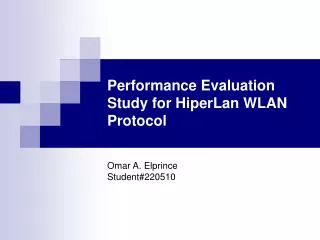
Performance Evaluation Study for IEEE 802.11 WLAN Protocol. Submitted to: Dr. Ashraf S Hasan Mahmoud Submitted by: Mohammad Abdur Razzaque(22030 Khawar Saeed Khan (220514). Objectives.

E N D
Performance Evaluation Study for IEEE 802.11 WLAN Protocol. Submitted to: Dr. Ashraf S Hasan Mahmoud Submitted by: Mohammad Abdur Razzaque(22030 Khawar Saeed Khan (220514)
Objectives • To provide an overview of IEEE 802.11 standard for WLAN including its details of MAC layer specifically different access schemes, its variants etc. • Performance Evaluation through Simulation
Why do we need Standard? • Multi vendors Compatibility • Protects Customers investment • High volumes reduce prices
Overview of IEE 802.11 • In recent years, much interest has been involved in the design of wireless networks for the local area communications. • Study group 802.11 was formed under IEEE Project 802 to recommend an international standard for Wireless Local Area Networks. • IEEE has standardized the 802.11 for wireless local area networks in 1990 .
Features of IEEE802.11 • Support of asynchronous and time-bounded delivery service • Continuity of service within extended areas via a distribution system, such as Ethernet. • Accommodation of transmission rates of 1 and 2- Mbps • Multicast (including broadcast) services • Network management services • Registration and Authentication services
Target environments • Inside buildings, such as offices, banks, shops, malls, hospitals, manufacturing plants, and residences. • Outdoor areas, such as parking lots, campuses, building complexes, and out-door plants
IEEE 802.11 Requirements • To be IEEE 802.11 standard compatible a device has fulfill the following requirements: • Single MAC supporting multiple PHYs • Mechanism to allow multiple overlapping networks in the same area • Provisions to handle the interface from other • ISM band radios and microwave ovens • Mechanism to handle “hidden” terminal problem • Options to support time-bounded services • Provisions to handle privacy and access security
IEEE 802.11 Topology • The 802.11 standard supports the following two topologies: • • Independent Basic Service Set (IBSS) networks • • Extended Service Set (ESS) networks • Independent Basic Service Set (IBSS) networks • smallest building block of a wireless LAN • stand-alone BSS, no backbone infrastructure and consists of at least two wireless stations • often referred to as an ad hoc network
IBSS • A basic service set may be isolated or it may connect to a backbone distribution system through an access point IBSS
ESS • An extended service set (ESS) consists of two or more basic service sets inter-connected by Distribution system • Typically, the distribution system is a wired backbone LAN. ESS
IEEE 802.11 services Services are divided into two groups: those that are part of every station, and those that are part of a DS: The service provided by stations is known as the station service. a) Authentication b) Deauthentication c) Privacy d) MSDU delivery
IEEE 802.11 servicescont….. The service provided by the DS is known as the distribution system service. a) Association b) Disassociation c) Distribution d) Integration e) Reassociation
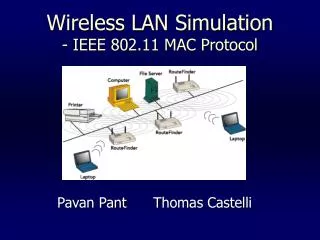
802.11 operation modes • Two operation modes defined in IEEE 802.11: Infrastructure Mode and Ad Hoc Mode • Infrastructure Mode: • At least one access point (AP) connected to the wired network infrastructure and a set of wireless end stations • An AP bridge or route the wireless traffic to a wired Ethernet network
802.11 operation modesCont.. • Ad-Hoc mode: • A set of 802.11 wireless stations that communicate directly with each other without using an access point or any connection to a wired network. • Ad-Hoc Mode is also called peer-to-peer mode or an Independent Basic Service Set (IBSS).
Variants of 802.11 • Up to present following are the variants of 802.11 and they all are same in MAC layer view but different PHYs. • IEEE802.11a: • OFDM @ 5 GHz U-NII bands – same as HIPERLAN-2 • Rates up to 54 Mb/s • IEEE802.11b: • CCK @ 2.4GHz • Rates up to 5.5 and 11 Mb/s • Same PLCP as IEEE802.11 DSSS
Variants of 802.11cont… • 802.11g: • Supporting PBCC (packet binary convolution coding, a single carrier technique) and OFDM. • Speed extension for the 802.11b standard. • Data rates up to 54 Mbps in the 2.4 GHz band. • 802.11d • The IEEE 802.11d TG d describes a protocol that will allow a 802.11 device to receive the regulatory information required to configure itself properly to operate anywhere on earth. • 802.11e • The 802.11e TG e is proceeding to build improved support for quality of service (for example for voice transmission).
IEEE 802.11 Logical Architecture • The logical architecture defines the network’s operation • 802.11 only defines the MAC and PHY layers • MAC layer is divided into MAC sublayer and MAC management sublayer entities • station management sublayer that is responsible for coordination of the interactions between MAC and PHY layers.
Carrier Sensing in 802.11 • PHY Sensing • Clear Channel Assessment (CCA) signal • Generate by the PLCP • Sensing: Detected data sensing or Carrier Sensing • Decision using detected bits slow but reliable • Decision using RSS of carrier against threshold – fast but many false alarms due to interference.
Carrier Sensing in 802.11Cont… • Virtual carrier sensing: • It is based on the reservation information found in the Duration field of all frames. • MAC Coordination will monitor the Duration field in all MAC frames and place this information in station's Network Allocation Vector (NAV)– indicates the medium is occupied for a given (length field) time duration. • If the NAV=0, then the channel is virtually free • Used for RTS/CTS and PCF based schemes mainly
IEEE802.11 MAC Layer • MAC has two sublayers and all the responsibilities are divided between them. • Major responsibilities of MAC sublayer: • Define access scheme • Define packet formats • Major responsibilities of management sublayer: • Support ESS • Power management • Security
Accessing the Wireless Medium • To access the medium, IEEE 802.11 provides different access schemes: • CSMA/CA – contention data • RTS/CTS – contention-free • PCF – contention-free, intended for time-bounded traffic • First two schemes are also referred as DCF(Distribution Coordination Function)
IFS (Inter Frame Spacing) DFIS: DCF-IFS (DIFS) used for contention data spacing that has the lowest priority and longest duration SIFS:Short IFS (SIFS), used for highest priority packets such as ACK and CTS (clear to send),has the lowest duration of time. PIFS: The PCF IFS (PIFS), designed for PCF operation, has the second priority rate with duration between DIPS and SIFS. DIFS PIFS SIFS Medium Busy Time IFS
CSMA/CA access Scheme • Procedure: • When a station ready for a new data frame transmission senses the channel status • If the channel is busy, the station defers its transmission and continues to sense the channel until it is idle. • If it is idle for DIFS period, the station choose a random number as a backoff timer.
CSMA/CA access Schemecont.. • The backoff timer is decreased by one for each idle slot • Stopped if the channel is sensed busy, and then reactivated if the channel is idle again and remains idle for more than a DIFS time duration. • When the backoff timer reaches zero, the data frame is transmitted.
RTS/CTS • RTS/CTS Operation: • When source is ready – RTS (20 bytes) is sent • Destination responds with CTS (16 bytes) after SIFS • Source terminal received CTS and after SIFS sends data • Destination terminal sends ACK after SIFS • Other terminal listening to RTS/CTS will turn their NAVsignal on – used for virtualcarrier sensing • NAV signal turned off when after the transmission and reception of the ACK frame
PCF (Point Coordination Function) • Optional MAC service – Not implemented by all manufacturers • Available only for infrastructure networks – not Ad-hoc • AP – point coordinator organizes periodical contention-free periods • (CFP) for delay-sensitive services • PCF operation • During PCF operation (part of CFP) NAV signal is on – • During the remainder of the CFP NAV signal is off and that can be used for contention
MAC frame Format of 802.11 Frame Control: This field carries control information being sent from station to station. Duration/ID: In most frames, this field contains a duration value, depending on the type of frame sent. Address 1, 2, .3,and 4: The address fields contain different types of addresses, depending on the type of frame being sent. Sequence Control: The sequence control is used for fragmentation numbering to control the sequencing. Body Field: This field has a variable length payload and its range is 0-2312 bytes. Frame Check Sequence (FCS): The MAC layer at the sending station calculates a 32 bits FCS using CRC and place the result in this field.
Physical Layer Architecture • Physical Layer has the following three components for each station: • Physical Layer management: • Channel tuningto different options within PHY • PLCP : • Carrier sensing • Forming packets for different PHYs • PMD: • Modulation, Coding
Physical Layer Technologies • Two main technologies are used for wireless communications: Radio Frequency and InfraRed. • For the Radio frequency there are two modulation schemes: • frequency hopping spread spectrum (FHSS) and • direct sequence spread spectrum (DSSS) • For InfraRed we use Diffused Infrared
FHSS • FHSS allows for a less complex radio design than DSSS. It has the following features: • FHSS PMD hops over 78 channels of 1 MHz each in the centre of the 2.44 GH ISM band • Modulation is GFSK: 1 bit/symbol 1 Mb/s or 2bit/symbol 2 Mb/s • Hopping rate: 2.5 hop per second • Therefore three APs can coexist in the same area which means maximum throughput of 6 Mb/s • Lowest cost and Power consumption • Most tolerant to signal interference
DSSS • The Direct Sequence Spread Spectrum (DSSS) has the following properties: • DSSS PMD uses 26 MHz chunks to transmit 11 Mc/s Modulation: DBPSK for 1 Mb/s and DQPSK for 2 Mb/s • ISM band at 2.4 GHz 11 overlapping channels with 5 MHz spacing • Max tx power = 100 mW • Wider range the FHSS • Highest cost and Power consumption
DFIR • Diffused Infrared has the following features • DFIR PMD utilizes 250 ns pulses • Pulse Position Modulation (PPM) • 16-PPM for the 1 Mb/s option • 4-PPM for the 2 Mb/s option • Low cost • Higher tolerance to RF signal interference • Lower range compare to spread spectrum
IEEE 802.11 DCF simulation • In this project we have simulated the IEEE 802.11 MAC layer’s Distributed coordination function (DCF) • The simulation is done using the standards defined by IEEE for 802.11
MODEL • Assumptions • Perfect channel conditions have been assumed • The packet propagation delays between the communicating stations are assumed to be zero • Only basic access is employed, no RTS/CTS messages are exchanged
We have studied the performance of 802.11 by subjecting it to different conditions • Parameters that were useful in the performance evaluation are • Number of Communication stations • Ranges of transmission • Frame sizes
Simulation Results • Our simulation calculates the following parameters • Total Transmissions • Successful Transmissions • Total Collisions • Unreachable Packets • Total Acknowledgments • Successful Acknowledgments • Acknowledgment Collisions • Unreachable Acknowledgments
Conclusion • It is clear that increasing the load in a WLAN system drastically reduces the efficiency of the network. • We propose to increase the transmission range for stations. Increasing the transmission range would improve the efficiency better for the heavy load
Proof • For the frame size 5, range 3 and No. Of Stations 10, the efficiency of network is 0.4423. If we increase the transmission range from 3 to 10, keeping the frame size 5 and No. Of Stations 10, the network efficiency comes close to 0.6. That is 15.77% improvement in efficiency.