Download
1 / 15
150 likes | 245 Views
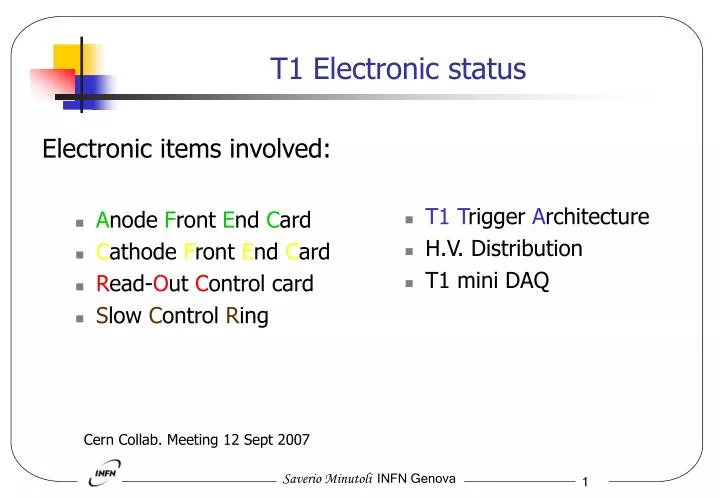
Electronic items involved: A node F ront E nd C ard C athode F ront E nd C ard R ead- O ut C ontrol card S low C ontrol R ing. T1 T rigger A rchitecture H.V. Distribution T1 mini DAQ. T1 Electronic status. Cern Collab. Meeting 12 Sept 2007.

E N D
Electronic items involved: Anode Front End Card Cathode Front End Card Read-Out Control card Slow Control Ring T1Trigger Architecture H.V. Distribution T1 mini DAQ T1 Electronic status Cern Collab. Meeting 12 Sept 2007
Ten different types (dimensions and connections). All schematics and layouts done. Ready for the mass production Production of some pcb types will start next week Preproduction of CSC-5P done. Installed on two CSCs at GIF and H8. Static tests done Routing and VFAT Hybrid Mech. matching Dynamic tests (to be complete): Compatibility with VFAT Preamp. stage Grounding and Shielding AFEC
Manage 64 chs The board has been completely debugged with a Digital Mezzanine developed by the Genoa group. The results obtained are compliant with the requirements. We have 8 cards fully equipped, enough to read-out 1.5 CSCs. To be tested with the digital VFAT. Minor pcb modifications for the mass production in progress. New version will hosts the R.H. low voltages regulator. CFEC (CMS chips) (1)
Manage 128 chs Static tests done Routing and VFAT Hybrid Mech. Matching Dynamic tests (to be done): Compatibility with VFAT Preamp. stage. new CFEC layout following the AFEC rules. We have 10 cards fully equipped, enough to read-out 3 CSCs. To be tested with the analog VFAT Hybrid. CFEC (VFAT hybrid) (2)
The design is almost fixed. Need some confirmations from W.S. or G.A about parts of the circuit !!!!!! Layout within 1 month board could be available middle/end of October. The ROC board manage two CSCs detectors. Collect the serial data streams coming out from the VFAT hybrids and transmit them to the Counting Room, via an optical link (1 GOH). Also the trigger bits are sent via optical links (2 GOHs). Hosts the Slow Control Ring node (CCUM), distribute to the FE electronic cards the I2C control line. Distribuite the power supply and the I2C lines to the new TOTEM DOHM. Control and generate the trigger bits logic transmission signal, and perform the trigger bits synchronization circuitry. Distribute and regenerate the Clock and T1 Fast Commands to all the FE boards. Hosts dedicate spy connectors for a mezzanine, in order to emulate the CCUM functions and acquire all the data and trigger bits coming out from the FE cards. The schematic is in progress, it inherits the skeleton of the T1 Digital Mezzanine design. ROC (1)
ROC (2) CRT4T C S C n DAV TR_MUX 1/0 BC0 CRT4T TR_VFAT C S C n+1 DAVs 1 LVDS2 CMOS 3 DAV_REDUNDANCY 8 10
ROC (3) I/O CCUM Has been tested (W.S.) ??? BC0b TR_GOH_DAV TRIGGER DAV MUX IDLEb/ON I/O CCUM I/O CCUM A CSC1 MUX DATA DAV K DATA_GOH_DAV K MUX A CSC2 MUX K
Based on the new TOTEM DOHM design (G.A.) Distributes the 40MHz LHC clock and serial Fast Commands (labeled as T1). Each SCR node manage and distribute the I2C communications lines. The I2C is the only way through what we can modify the setting parameters of the major electronic devices (VFAT included) involved in the FE Totem project. According documentation the I2C limitations are: The maximum number of nodes (~11). The maximum cable length (50cm/branch, 2-3m in total). Slow Control Ring (1)
Slow Control Ring (2) TOTEM DOHM ROCs I2C – P.S. I2C ¼ T1
All the trigger bits generated by the T1 detector are sent to the Totem Trigger System via optical link. T1 detector modularity is ¼, this means 15 CSCs chambers. Each CSC generate 16 trigger bits 1 GOL. Globally ¼ T1 needs 15 fibers to be able to transfer all the trigger information. No spare GOL channels available. The trigger bits sent to the Counting Room, will be collected on the Trigger TOT-FED, that can manage 36 fibers, shared in three groups of 12 fibers each. We have 15 fibers per each ¼ T1. In order to merge and manipulate with a dedicate algorithm all the trigger bits, we will need a mezzanine (to be defined) to add to the Trigger TOT-FED. The trigger system is not completely fixed, need some more iterations within the trigger group. T1Trigger Architecture (1)
12 12 3 3 3 3 12 12 T1 TRG_TOTFED T1 TRG_TOTFED T1Trigger Architecture Trigger Bits 2 x 480 = 960 VFAT VFAT (16bits) 8bits 8bits (16bits) ~6k wires 8 8 ~6k wires CAVERN x2 x2 1 1 CSC 2 2 CSC x2 x2 30 30 x15 x15 ROC ROC T1 ARM T1 ARM GLOBAL TRG_TOTFED Y X X (Needs TRG algo.) LV1 COUNTING ROOM
In order to have a back-up solution for H8 and bld.188, we are setting up a small and portable DAQ system to read one VFAT hybrid. The system performs the I2C protocol functionalities. The slow commands are managed through a PC and a custom software. The implementation of the all VFAT commands is in progress. The system hosts a DCU device to read back the VFAT internal DACs registers. The VFAT serial data-out will be acquired by a FPGA that decodes the data and sends the information out to the PC via an USB port. The trigger bits are manipulated by the same FPGA. The system can generate the clock and T1 commands locally or remotely. The system is based on the T1 Digital Mezzanine. A possible extension of the system to read an entire chamber (using several T1 D.M. already available) is under evaluation. Most of the pieces are available (HW, FW), expected to be available within October. T1 mini DAQ back-up (1)
VFAT CSC compatibility verification AFEC ready CFEC (both types) need to be tested with CSC New designs can be ready within a month. ROC available middle/end October Mini DAQ ready within October H.V.(CAEN) and L.V.(WIENER) ready to be purchased Need to procure the CERN components: R.H. logic devices (lvds_mux, lvdsbuf, crt902, crt4t, crt245 …) GOH 7.3, etc…. CSCs test in progress to the H8 test beam Finally some inputs have been read with VFAT through the DAQ in H8 Small, but important results obtained. Conclusions