Download
1 / 23
240 likes | 309 Views
The Ethernet physical layer is the physical layer component of the Ethernet standard.<br>The Ethernet physical layer evolved over a considerable time span and encompasses quite a few physical media interfaces and several magnitudes of speed. The speed ranges from 1 Mbit/s to 100 Gbit/s in speed while the physical medium can range from bulky coaxial cable to twisted pair to optical fiber. In general, network protocol stack software will work similarly on all of the following types.<br>10 Gigabit Ethernet is becoming more popular in both enterprise and carrier networks, with 40 Gbit/s and 100 Gbit/s Ethernet now ratified. Higher speeds are under development. Metcalfe now believes commercial applications using terabit Ethernet may occur by 2015 though he says existing Ethernet standards may have to be overthrown to reach terabit Ethernet.ThesisScientist.com

E N D
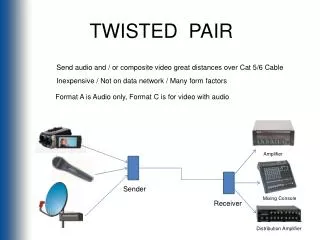
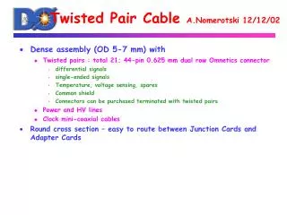
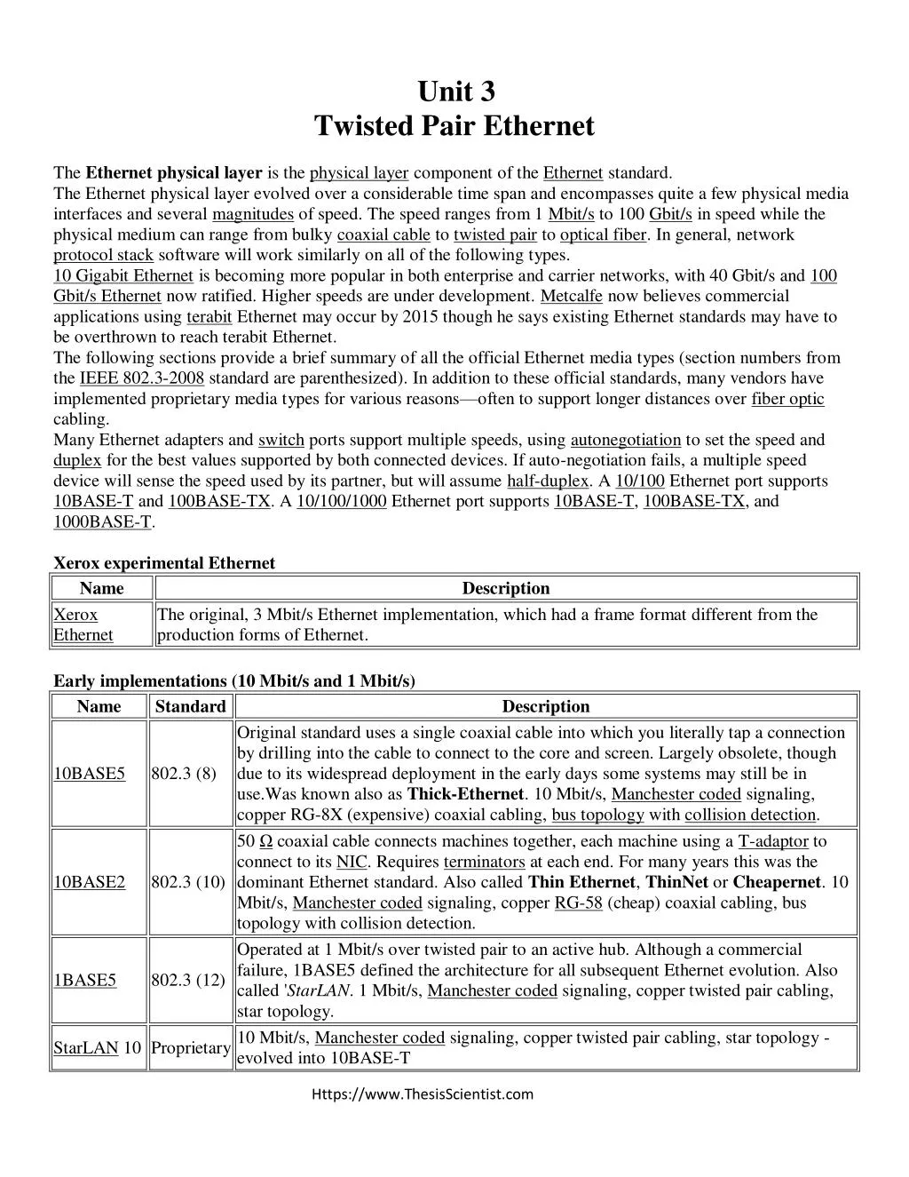
Unit 3 Twisted Pair Ethernet The Ethernet physical layer is the physical layer component of the Ethernet standard. The Ethernet physical layer evolved over a considerable time span and encompasses quite a few physical media interfaces and several magnitudes of speed. The speed ranges from 1 Mbit/s to 100 Gbit/s in speed while the physical medium can range from bulky coaxial cable to twisted pair to optical fiber. In general, network protocol stack software will work similarly on all of the following types. 10 Gigabit Ethernet is becoming more popular in both enterprise and carrier networks, with 40 Gbit/s and 100 Gbit/s Ethernet now ratified. Higher speeds are under development. Metcalfe now believes commercial applications using terabit Ethernet may occur by 2015 though he says existing Ethernet standards may have to be overthrown to reach terabit Ethernet. The following sections provide a brief summary of all the official Ethernet media types (section numbers from the IEEE 802.3-2008 standard are parenthesized). In addition to these official standards, many vendors have implemented proprietary media types for various reasons—often to support longer distances over fiber optic cabling. Many Ethernet adapters and switch ports support multiple speeds, using autonegotiation to set the speed and duplex for the best values supported by both connected devices. If auto-negotiation fails, a multiple speed device will sense the speed used by its partner, but will assume half-duplex. A 10/100 Ethernet port supports 10BASE-T and 100BASE-TX. A 10/100/1000 Ethernet port supports 10BASE-T, 100BASE-TX, and 1000BASE-T. Xerox experimental Ethernet Name Xerox Ethernet production forms of Ethernet. Early implementations (10 Mbit/s and 1 Mbit/s) Name Standard Original standard uses a single coaxial cable into which you literally tap a connection by drilling into the cable to connect to the core and screen. Largely obsolete, though due to its widespread deployment in the early days some systems may still be in use.Was known also as Thick-Ethernet. 10 Mbit/s, Manchester coded signaling, copper RG-8X (expensive) coaxial cabling, bus topology with collision detection. 50 Ω coaxial cable connects machines together, each machine using a T-adaptor to connect to its NIC. Requires terminators at each end. For many years this was the dominant Ethernet standard. Also called Thin Ethernet, ThinNet or Cheapernet. 10 Mbit/s, Manchester coded signaling, copper RG-58 (cheap) coaxial cabling, bus topology with collision detection. Operated at 1 Mbit/s over twisted pair to an active hub. Although a commercial failure, 1BASE5 defined the architecture for all subsequent Ethernet evolution. Also called 'StarLAN. 1 Mbit/s, Manchester coded signaling, copper twisted pair cabling, star topology. StarLAN 10 Proprietary 10 Mbit/s, Manchester coded signaling, copper twisted pair cabling, star topology - evolved into 10BASE-T Description The original, 3 Mbit/s Ethernet implementation, which had a frame format different from the Description 10BASE5 802.3 (8) 10BASE2 802.3 (10) 1BASE5 802.3 (12) Https://www.ThesisScientist.com
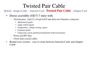
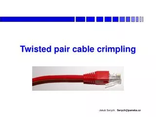
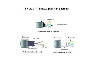
LattisNet UTP Proprietary 10 Mbit/s, Manchester coded signaling, copper twisted pair cabling, star topology - evolved into 10BASE-T Runs over four wires (two twisted pairs) on a Category 3 or Category 5 cable. An active hub or switch sits in the middle and has a port for each node. This is also the configuration used for 100BASE-T and gigabit Ethernet. Manchester coded signaling, copper twisted pair cabling, star topology - direct evolution of 1BASE-5. Early Ethernet standards used Manchester coding so that the signal was self-clocking not adversely affected by high-pass filters. Twisted-pair Ethernet Several varieties of Ethernet were specifically designed to run over 4-pair copper structured cabling already installed in many locations. ANSI recommends using Category 6 cable for new installations. RJ-45 Wiring (TIA/EIA-568-B T568A) Pin Pair Color telephone 10BASE-T 100BASE-TX 1000BASE-T PoE mode A PoE mode B 1 3 white/green - TX+ z 2 3 green - TX- z 3 2 white/orange - RX+ z 4 1 blue ring - - 5 1 white/blue tip - - 6 2 orange - RX- z 7 4 white/brown - - - 8 4 brown - - - Combining 10Base-T (or 100BASE-TX) with "IEEE 802.3af mode A" allows a hub to transmit both power and data over only two pairs. This was designed to leave the other two pairs free for analog telephone signals. The pins used in "IEEE 802.3af Mode B" supplies power over the "spare" pairs not used by 10BASE-T and 100BASE-TX. In a departure from both 10BASE-T and 100BASE-TX, 1000BASE-T uses all four cable pairs for simultaneous transmission in both directions through the use of echo cancellation. Ethernet minimum cable lengths All copper Ethernet segments that run the collision detection (CD) portion of CSMA/CD have a minimum cable length to function properly because of reflections. This applies only to 10BASE-T and 100BASE-TX standards; The 1000BASE-TX standard is covered at the end of this section. Fiber connections have minimum cable lengths due to level requirements on received signals.[11] Fiber ports designed for long-haul wavelengths require a signal attenuator if used within a building. Industrial Ethernet applications use a star topology with no collisions so that no minimum cable length is required. 1000BASE-TX supports half-duplex mode, making collisions possible. Consequently, the 1000BASE-TX standard requires a minimum cable length for collision detection to function properly; to avoid this in Gigabit Ethernet, small frames are padded into the transmission in half-duplex mode.[12] Related standards Networking standards that are not part of the IEEE 802.3 Ethernet standard, but support the Ethernet frame format, and are capable of interoperating with it. oLattisNet—A SynOptics pre-standard twisted-pair 10 Mbit/s variant. 10BASE-T 802.3 (14) bidi bidi bidi bidi bidi bidi bidi bidi 48V out 48V out 48V return - - 48V return - - - - - 48V out 48V out - 48V return 48V return Https://www.ThesisScientist.com
o100BaseVG—An early contender for 100 Mbit/s Ethernet. It runs over Category 3 cabling. Uses four pairs. Commercial failure. oTIA 100BASE-SX—Promoted by the Telecommunications Industry Association. 100BASE-SX is an alternative implementation of 100 Mbit/s Ethernet over fiber; it is incompatible with the official 100BASE-FX standard. Its main feature is interoperability with 10BASE-FL, supporting autonegotiation between 10 Mbit/s and 100 Mbit/s operation – a feature lacking in the official standards due to the use of differing LED wavelengths. It is targeted at the installed base of 10 Mbit/s fiber network installations. oTIA 1000BASE-TX—Promoted by the Telecommunications Industry Association, it was a commercial failure, and no products exist. 1000BASE-TX uses a simpler protocol than the official 1000BASE-T standard so the electronics can be cheaper, but requires Category 6 cabling. oG.hn—A standard developed by ITU-T and promoted by HomeGrid Forum for high-speed (up to 1 Gbit/s) local area networks over existing home wiring (coaxial cables, power lines and phone lines). G.hn defines an Application Protocol Convergence (APC) layer that accepts Ethernet frames and encapsulates them into G.hn MSDUs. Networking standards that do not use the Ethernet frame format but can still be connected to Ethernet using MAC-based bridging. o802.11—A standard for wireless local area networks (LANs), often paired with an Ethernet backbone. o802.16—A standard for wireless metropolitan area networks (MANs), including WiMAX 10BaseS—Ethernet over VDSL Long Reach Ethernet Avionics Full-Duplex Switched Ethernet TTEthernet — Time-Triggered Ethernet for design of mixed-criticality embedded systems Metro Ethernet Evolution Ethernet is an evolving technology. Evolutions have included higher bandwidth, improved media access control methods, and changes to the physical medium. Ethernet evolved into the complex networking technology that today underlies most LANs. The coaxial cable was replaced with point-to-point links connected by Ethernet repeaters or switches to reduce installation costs, increase reliability, and enable point-to-point management and troubleshooting. There are many variants of Ethernet in common use. Ethernet stations communicate by sending each other data packets, blocks of data that are individually sent and delivered. As with other IEEE 802 LANs, each Ethernet station is given a 48-bit MAC address. The MAC addresses are used to specify both the destination and the source of each data packet. Network interface cards (NICs) or chips normally do not accept packets addressed to other Ethernet stations. Adapters come programmed with a globally unique address. Despite the significant changes in Ethernet from a thick coaxial cable bus running at 10 Mbit/s to point-to-point links running at 1 Gbit/s and beyond, all generations of Ethernet (excluding early experimental versions) use the same frame formats (and hence the same interface for higher layers), and can be readily interconnected through bridging. Due to the ubiquity of Ethernet, the ever-decreasing cost of the hardware needed to support it, and the reduced panel space needed by twisted pair Ethernet, most manufacturers now build the functionality of an Ethernet card directly into PC motherboards, eliminating the need for installation of a separate network card. Shared media Https://www.ThesisScientist.com
A 1990s network interface card supporting both coaxial cable-based 10BASE2 (BNC connector, left) and twisted pair-based 10BASE-T (8P8C connector, right). Ethernet was originally based on the idea of computers communicating over a shared coaxial cable acting as a broadcast transmission medium. The methods used were similar to those used in radio systems, with the common cable providing the communication channel likened to the Luminiferous Aether in 19th century physics, and it was from this reference that the name "Ethernet" was derived. Original Ethernet's shared coaxial cable (the shared medium) traversed a building or campus to every attached machine. A scheme known as carrier sense multiple access with collision detection (CSMA/CD) governed the way the computers shared the channel. This scheme was simpler than the competing token ring or token bus technologies. Computers were connected to an Attachment Unit Interface (AUI) transceiver, which was in turn connected to the cable (later with thin Ethernet the transceiver was integrated into the network adapter). While a simple passive wire was highly reliable for small networks, it was not reliable for large extended networks, where damage to the wire in a single place, or a single bad connector, could make the whole Ethernet segment unusable. Since all communications happen on the same wire, any information sent by one computer is received by all, even if that information is intended for just one destination. The network interface card interrupts the CPU only when applicable packets are received: The card ignores information not addressed to it. Use of a single cable also means that the bandwidth is shared, so that network traffic can be very slow when many stations are simultaneously active. Collisions reduce throughput by their very nature. In the worst case, when there are lots of hosts with long cables that attempt to transmit many short frames, excessive collisions can reduce throughput dramatically. However, a Xerox report in 1980 summarized the results of having 20 fast nodes attempting to transmit packets of various sizes as quickly as possible on the same Ethernet segment. The results showed that, even for the smallest Ethernet frames (64 Bytes), 90% throughput on the LAN was the norm. This is in comparison with token passing LANs (token ring, token bus), all of which suffer throughput degradation as each new node comes into the LAN, due to token waits. This report was controversial, as modeling showed that collision-based networks became unstable under loads as low as 40% of nominal capacity. Many early researchers failed to understand the subtleties of the CSMA/CD protocol and how important it was to get the details right, and were really modeling somewhat different networks (usually not as good as real Ethernet). Repeaters and hubs For signal degradation and timing reasons, coaxial Ethernet segments had a restricted size. Somewhat larger networks could be built by using an Ethernet repeater. Initial repeaters had only 2 ports, but they gave way to 4, 6, 8, and more ports. People recognized the advantages of cabling in a star topology, primarily that a fault in one of the legs affects operation of only the stations attached to that leg. Https://www.ThesisScientist.com
A twisted pair Cat-3 or Cat-5 cable is used to connect 10BASE-T Ethernet Ethernet on unshielded twisted-pair cables (UTP), beginning with StarLAN and continuing with 10BASE-T, was designed for point-to-point links only, and all termination was built into the device. This changed repeaters from a specialist device used at the center of large networks to a device that every twisted pair-based network with more than two machines had to use. The tree structure that resulted from this made Ethernet networks more reliable by preventing faults with one peer or its associated cable from affecting other devices on the network. Despite the physical star topology, repeater based Ethernet networks still use half-duplex and CSMA/CD, with only minimal activity by the repeater, primarily the Collision Enforcement signal, in dealing with packet collisions. Every packet is sent to every port on the repeater, so bandwidth and security problems are not addressed. The total throughput of the repeater is limited to that of a single link, and all links must operate at the same speed. iBase 5 I2 iBase 5is i2‘s investigative database. It provides capabilities to configure the database, capture the data, and perform analysis all in a controlled environment; it fully integrates with i2 There are two versions: iBase Basic which stores its data in Microsoft Microsoft SQL Server. This document provides information for both products. You do not need to uninstall your existing i2 software before installing i2 iBase 5. Existing i2 iBase 4 security files and databases must be upgraded for use with i2 iBase 5. For details of upgrading and compatibility with previous versions and other i2 products. Warning and Disclaimer i2 provides this document "as is", without representation or warranty of any kind, express or implied, including without limitation any warranty concerning the accuracy, adequacy, or completeness of such information contained herein. i2 does not assume responsibility for the use or inability to use the software product as a result of providing this information. The data presented in this document is fictitious and for illustration purposes only with no connection to, without limitation, past or present persons, organizations, identifying numbers, or circumstances, except by coincidence. Release Contents The iBase 5 release includes the following program features—some of which are separately licensed: Program feature Description i2 iBase 5 Use i2 iBase 5 to work with MS Access databases. SQL Server Enabled Use i2 iBase 5 to work with either MS Access or SQL Server databases. Access, and iBase Standard which can use either Microsoft Access or Https://www.ThesisScientist.com
Designer Use i2 iBase 5 Designer to design and administer iBase databases and security files. Use Audit Viewer and other tools to maintain iBase databases. Use i2 iBase 5 Scheduler to schedule batch imports and exports. Tools Scheduler Coordinate Extensions Schema Update Use i2 iBase 5 to store data entered using multiple coordinate systems, in the same iBase database. Use i2 iBase 5 to update database schemas from a template (requires i2 iBase 5 Designer). Use Microsoft SQL Server merge replication to enable distributed use of iBase (requires the SQL Server Enabled feature). Database Replication i2 Interfaces 2 Administration Center iBase GIS Interface to GIS products. See the i2 iBase GIS Interfaces 2 Release Notes for details. Documentation for iBase administrators. What’s New in This Release? iBase 5 is a major product release that includes new features and enhancements. In addition, this release also addresses several bugs reported in previous releases. The following table summarizes the iBase 5 releases: Version Release Date i2 iBase 5.0.5 (inc. SP1) April 2008 i2 iBase 5.0.3 October 2007 i2 iBase 5.0.1 June 2007 iBase 5.0.5 (inc. SP1) i2 iBase 5.0.5 (inc. SP1) resolves issues discovered since the release of i2 Base 5.0.3, and includes the following new and updated features: Strong Passwords In previous versions of iBase it was not possible to use non A-Z or 0–9 characters for SQL server login names or passwords in the iBase connection file when using SQL standard security. i2 iBase 5.0.5 (including SP1) now supports stronger login name and password combinations, based on the characters from the ASCII character set in the range 0 to 127. This includes many of the characters that are used to generate stronger passwords, including & $ * and _. You can see the available characters at the following location http://www.asciitable.com. Notes: SQL Server doesn't permit the use of the full 0-127 range of characters in login names and passwords (an error message will be displayed). ―Extended‖ ASCII characters are not supported. MapInfo 9 i2 iBase 5.0.5 (inc. SP1) adds supports for MapInfo 9.0, while still supporting earlier versions of MapInfo 7.8, 8.0 and 8.5. Https://www.ThesisScientist.com
Northgate Blue 8 XD 1.3 SP1 i2 iBase 5.0.5 (inc. SP1) is compatible with Northgate Blue 8 XD 1.3 SP1, as well as the previously compatible version 1.2.9 build 12. Updated Help and Importing Guide There have been some updates to the online help files. A new edition of the i2 iBase Importing Guide is also included. iBase 5.0.3 iBase 5.0.3 resolved issues discovered since the release of iBase 5.0.1. Details of the issues resolved by iBase 5.0.3 were listed in the following technical alert: • i2 iBase 5 Hotfix 1 TA24 This document was included as a component of the hotfix. iBase 5.0.1 Enhancements for system administrators The Windows (MSI) compliant installer speeds up the installation of iBase and allows integration with enterprise application deployment technologies. It is now possible to copy and keep synchronized the schema of a main database, for example, at a head office, with copies of the database on remote machines or laptops. The separately licensed Schema Update tool allows the schema of the copy databases, including their folder objects, to be synchronized with changes made in a main database. A new online documentation resource, the Administration Center, is specifically designed for people who need to administer iBase databases; installation is optional. Enhancements for database designers You can create SQL Server databases that are partitioned by case. Access to records is controlled on a case-by- case basis. Users can perform analysis on a single case using read/write access, or across multiple cases using a read-only Multi-Case Analysis mode. You can improve the usability of your database design (and the consistency of the data) by adding filtered pick lists where the list item selected by the user controls what subsequent options are available. This can speed up data entry and reduce the number of data entry errors. The facility to add descriptions to entity and link types for display as tooltips in iBase also reduces errors by helping users to select the correct types. You can now enter coordinate data that is based on more than one coordinate system, and convert it to a standard format. Coordinates in the standard format can be used to plot points on maps, and iBase users can perform queries to find items in a defined area or near a specified place. Input of this data requires a special Coordinate field type. These features are separately licensed. A new manual, the i2 iBase 5 Designer Guide, is also provided. Improved usability for data entry users and analysts Changes in the areas of queries, pick lists, icons, folder objects and reporting are intended to make data entry and analysis more accurate. When querying data, specific records can be excluded from the results of the query. Complex operations, such as building up a report in Microsoft Access format, is now made more efficient. In Full-Text Search, the scope of searches can be narrowed to just the fields likely to hold the data for which the user is searching; these field selections can be saved for re-use. Https://www.ThesisScientist.com
Improved performance Performance is improved in some areas so that operations such as performing queries, batch deletion, and duplicate checking can be completed more quickly in some circumstances. In particular, bulk import (SQL Server 2005 databases only) speeds up large data imports—bulk importing is particularly suited to operations such as overnight updates of large databases using iBase Scheduler, at times when there are no users accessing the databases. Closer integration between iBase and TextChart iBase and TextChart are now fully integrated. The streamlined facilities allow for a direct real-time connection between TextChart 3 and the iBase 5 database to ensure that unstructured text can be rapidly entered into the iBase database. power2 enhancements There are some additions to the power2 functionality. Users in SQL Server databases, can search for people‘s names and return results using lists of name variants, to find all the different spellings and variations of a name. They can also use semantic types in queries. For example, they can search on ―Person‖ as shorthand for all entity types that are assigned the Person semantic type such as Policeman, Fire crew, Victim, Nominal, Suspect or Witness. Semantic queries can be chained with traditional iBase queries. Semantic types are now used in the iBase Browse and Records dialogs. Notes for existing users iBase 5 uses the same dongle permits as iBase 4. Therefore existing users do not require a replacement dongle. A dongle exchange will however be required for customers using additional license options. Documentation and Examples The manuals and online help for iBase are updated for this release. With the exception of the Administration Center, the manuals and help are automatically installed with the product. Shortcuts for the documentation are provided on the Windows Start menu under the i2 ► i2 iBase 5 ► Documentation program group. Administration Center Information specifically for administrators of iBase is provided in the Administration Center. This online documentation can be installed by selecting the Custom installation option; installation is optional. An Administration Center shortcut will be added to the Start menu under the i2 ► i2 iBase 5 ► Documentation program group. The Administration Center can also be run from the CD. To run it, double-click on AdministrationCenter.chm in the Administration Center folder. Note: The Administration Center must be run on a local drive—you cannot view its contents over the network. Manuals There is a new i2 iBase 5 Designer Guide for this release. The other manuals in the documentation set are also updated. All manuals are supplied in PDF format: Manual Title Part Number i2 iBase 5 Quick Start Guide 1252 i2 iBase 5 User Guide 1255 i2 iBase 5 Importing Guide 1851 i2 iBase 5 Reporting Guide 1257 i2 iBase 5 Designer Guide 1258 Https://www.ThesisScientist.com
White papers The following white papers are available. Those available on the CD are in the White Papers folder. The others are available from your supplier. White Paper Title Part Number 1303 1406 1405 1304 On the CD? i2 iBase 5 Product Overview What’s New in i2 iBase 5 Upgrading to i2 iBase 5 and i2 Analyst’s Workstation 3 Using i2 iBase 5 with i2 TextChart3 i2 iBase 5 Database Replication Product Overview White Paper 1389 i2 iBase 5 Database Replication Deployment Guide White Paper 1396 Using i2 iBase 5 in a Distributed Environment White Paper Yes 1390 Examples An example database called Designer Guide is installed with the product for use with the i2 iBase 5 Designer Guide; instructions for setting up the database are given in the manual. An example database called User Guide is installed with the product for use with manuals such as the i2 iBase 5 User Guide. To use this: 1.Select the following from the Windows Start menu: All Programs ► i2 ► i2 iBase 5 ► Documentation ► i2 iBase 5 User Guide Database. The first time you use it, the Examples folder is copied to your application data area and a shortcut is placed in the My Documents folder (on Windows XP) or in the User's Files\Documents folder (on Windows Vista). The database, User Guide.idb, is opened from an i2\i2 iBase 5\Examples subfolder. 2.Log on to the security file User Guide.ids. These are the standard user IDs: User ID Password Role general general A user with all the permissions required to work through the i2 iBase 5 User Guide, the i2 iBase 5 Reporting Guide, and the i2 iBase 5 Importing Guide. SYSADMIN SYSADMIN A full system administrator with all the permissions required to work through the i2 iBase 5 Designer Guide. DataEntry DataEntry A Data Entry User with restricted menu functionality and access to fewer links. An analytical user with read-only access. Analyst Analyst Moving the User Guide database If you move the User Guide database from its default location, you will need to open it in iBase Designer to re- register the location of the security file which controls it. This is standard iBase behavior. Reverting to a clean version of the User Guide database If you are using a Microsoft Access database and you want to revert to the version of the User Guide database shipped with the product: 1. Select the following from the Windows Start menu: All Programs ► i2 ► i2 iBase 5 ► Tools ► Reset i2 iBase 5 User Guide Database. Https://www.ThesisScientist.com
2. Click Yes when prompted to reset the database. Warning: Reverting to an unmodified User Guide database will mean that you will lose any changes that you made. For example, you will delete all entities, links, sets, queries, and other folder objects that you created or modified. This command does not remove SQL Server databases. Using the User Guide database with SQL Server The User Guide database is shipped as a Microsoft Access database and can be used with iBase. However, if you want to follow the examples in the i2 iBase 5 User Guide that demonstrate how to use Full-Text Searches, queries with distinct counts, cases and queries with semantic conditions, then you will need to upsize this to SQL Server format and build a Full-Text search index for all fields of all entity and link types. Each user will need their own copy of the database. The following instructions assume that you have a working installation of iBase prior to installing the example databases, and that you have permission to create a database on your SQL Server machine. See the Administration Center for information on how to do this and for further details about the steps described below. To upsize the User Guide database: 1. Check that the server does not have an existing database called User Guide. If it does, rename the User Guide.idb file, for example to User Guide 2.idb. You will also need to rename the other files associated with the database (with the suffixes .dot, .doc, .ant and .idx). 2. Copy the User Guide Database folder to a suitable place. It is located in: C:\Program Files\i2 iBase 5\Resources\<language>\Examples\ User Guide Database 3. Start iBase Designer, and then log on to the security file User Guide.ids as user SYSADMIN and cancel the option to open a database or create a new one. 4. From the Tools menu, select Upsize ► Database to SQL Server. 5. Accept the option to make a backup. 6. Enter the name of the SQL Server machine and a login and password that has the dbcreator role on the server. Do not use the server name (local) since other clients will not be able to use the database. This server name is intended only for local use on the server computer. If the database name does not appear when you refresh the list, type in the machine name of the server. 7. Click Finish. The database will be copied to the server using the name of the .idb file and the .idb file will become a connection file for the database. 8. In iBase Designer, use the option Full-Text Search Indexing on the Tools menu to build a full index for all fields of all entities and links. For further information, refer to the Administration Center or the online help. You can now use the database by starting iBase, and from the File menu, selecting Open Database. For information on using the User Guide database with i2 Data Miner, see the Administration Center document Setting up Data Miner. Utilities The following utilities are available with iBase 5. The utilities are accessible from the Windows Start menu in the i2 ► i2 iBase 5 ► Tools program group. i2 iBase 5 Database Configuration (SQL Server databases only) Https://www.ThesisScientist.com
You can use the Database Configuration utility to manage connections to SQL Server databases, specifically to set the server name, server login name and the use of Windows security. You can only use the utility with databases upgraded to or created for iBase 5. Note: To manage the connection to an SQL Server database created for iBase 4, you must use the SQLDBConfig utility supplied with iBase 4 or Analyst's Workstation 2. i2 iBase 5 Repair Compact You can use the Repair Compact utility to repair a damaged iBase 5 Access database. This utility can also be run from the Tools menu in iBase Designer. i2 iBase 5 Scheduler Configuration The Scheduler Configuration dialog allows administrators to set up Scheduler for running batch imports and exports. i2 iBase 5 Audit Viewer You can use Audit Viewer to view and manage audit logs for database and security files. Installation Before installing iBase 5, please check that your system meets all the requirements described in System Requirements on page 5. Compatibility notes iBase 5 can be installed in parallel to iBase 4 so that both versions can run on the same machine. However, iBase 5 databases are not compatible with iBase 4–any existing iBase 4 databases and security files that you want to use with this release must be upgraded. See page 14 for details. iBase 5 is compatible with the following i2 applications: Analyst’s Notebook iBase 5 is compatible with Analyst's Notebook 7. Note: You can open charts created with iBase 4 and Analyst’s Notebook 6. When you open the chart, any iBase 4 chart items are automatically converted to iBase 5. The database does not have to be open. iBase GIS Interfaces iBase 5 is compatible with iBase GIS Interfaces 2. TextChart iBase 5 is compatible with TextChart 3. • iBase 5 will load visualizations and validate templates from earlier versions of TextChart (v1.0.5, 1.1.55 and 2.0.1). • iBase 5 will only create templates for use with TextChart 3. These templates are not compatible with previous versions of TextChart. TextChart and iBase must be installed on the same machine if you want to use live connections to iBase databases. TextChart does not need to be installed on the same machine as iBase if you load data from visualizations (as in previous releases). iBase Database Replication iBase Database Replication requires that you choose the SQL Server Enabled feature in the installer. Non- replicated databases can use a replicated security file, provided the databases are iBase 5 databases. Https://www.ThesisScientist.com
iBase Database Replication has no effect on how you use Extended Access Control with iBase. However, it is essential to replicate the security file if you use Extended Access Control within a replicated environment. Failure to do so will undermine the additional security provided by Extended Access Control. If you use iBase GIS Interfaces then each site that uses a mapping application must install iBase GIS Interfaces and set up its own mapping configurations. Mapping configurations are not replicated. iBase Database Replication may not be used with iBase Scheduler or Analyst’s Workstation. Installation steps Please read the i2 iBase GIS Interfaces 2 Release Notes before installing iBase as it is important to install i2 and third-party applications in the correct order. Using Setup.exe To install iBase 5: 1. Log on to the machine on which you are installing as a local administrator. 2. Close all applications that you may have open. 3. If present remove any USB Authorization Device (Dongle). 4. Insert the product CD into the computer‘s CD drive. The installation will start automatically. If it does not start automatically, you need to browse to the CD and run Setup.exe in the i2 iBase 5 folder. 5. Follow the prompts. You will be asked for the setup type: Basic user Allows the user to work with MS Access databases only. Select Custom to install iBase Designer. Standard user Custom to install iBase Designer. Custom Allows you to install the optional parts of iBase, such as iBase Designer, iBase GIS Interfaces, any of the tools or utilities, and/or the Administration Center. Notes: For blue 8 world, you must install the interfaces while logged on as the user who will run the interface—this user needs to be a local administrator. Note: We recommend that you install the Administration Center on machines used by system and database administrators as you may need to refer to it in order to set up and configure your installation. 6. Follow the prompts to complete the installation. The installer will install these shortcut folders: i2 ► i2 iBase 5 ► Start iBase. i2 ► i2 iBase 5 ► Documentation and product documentation in PDF format. Allows the user to work with either MS Access or SQL Server databases. Select Access the Administration Center (if installed), example databases Starts iBase Designer and iBase utilities, such as Scheduler and Audit Viewer. i2 ► i2 iBase 5 ► Tools Automated and silent installs To install an i2 product with all of its default settings, but with no need for intervention from the user, you can perform a "silent install" like this: Setup.exe /s /v/quiet Https://www.ThesisScientist.com
In terms of the installed product, issuing this command has the same effect as double-clicking the file and giving the simplest possible (affirmative) response to every question. However, the user sees no feedback at all about the installation process until the product shortcut appears on the Start menu. To provide the user with a little more information about what is happening to their computer (but still using default options, and allowing no intervention), you can use /passive instead of /quiet: Setup.exe /s /v/passive For more details refer to the i2 Products Packaging and Deployment Guide. Using Windows Installer (MSI) This version of iBase is available as an MSI Package. For more details on installing using Windows Installer please refer to the i2 Products Packaging and Deployment Guide. Third party software Installing iBase installs third party software. For full details of the third party software installed and how to prevent its installation, refer to the i2 Products Packaging and Deployment Guide. Microsoft .NET Framework language packs In order to have Microsoft .NET Framework information dialogs displayed in a local language you need to install a corresponding language pack. You can download Microsoft .NET Framework version 2 language packs from the Microsoft Web site: http://www.microsoft.com/downloads/details.aspx?FamilyID=39c8b63b-f64b-4b68-a774- b64ed0c32ae7&DisplayLang=en. Language specific files The user locale setting controls the installation of language specific files and folders. For more details, refer to the i2 Products Packaging and Deployment Guide. Customizing installed files For information on customizing installed files, please refer to the i2 Products Packaging and Deployment Guide. Configuring an installation of iBase 5 Information on setting up your installation is available in the Administration Center. Setting up client machines on Windows Vista Any user who sets up iBase on client machines running Windows Vista will require modify permissions on the file i2\i2 iBase 5\<language>\Settings\settings.xml. This permission is required even if the user is a member of the Administrator group. iBase Scheduler Before attempting to configure Scheduler, we recommend that you read the Administration Center document Setting Up iBase Scheduler which provides guidance on setting up this utility. Near field communication or NFC Near field communication, or NFC, is a set of short-range wireless technologies, typically requiring a distance of 4cm or less. NFC operates at 13.56 MHz and at rates ranging from 106 kbit/s to 848 kbit/s. NFC Https://www.ThesisScientist.com
communication always involves an initiator and a target: the initiator actively generates an RF field that can power a passive target. This enables NFC targets to take very simple form factors such as tags, stickers, key fobs, or cards that do not require batteries. NFC peer-to-peer communication is also possible, where both devices are powered. Essential specifications As with proximity card technology, near-field communication is mediated by magnetic induction between two loop antennas located within each other's near field, effectively forming an air-core transformer. It operates within the globally available and unlicensed radio frequency ISM band of 13.56 MHz. Most of the RF energy is concentrated in the allowed 14 kHz bandwidth range, but the full spectral envelope may be as wide as 1.8 MHz when using ASK modulation.[1] Working distance with compact standard antennas: up to 20 cm Supported data rates: 106, 212, 424 or 848 kbit/s There are two modes: oPassive Communication Mode: The Initiator device provides a carrier field and the target device answers by modulating the existing field. In this mode, the Target device may draw its operating power from the Initiator-provided electromagnetic field, thus making the Target device a transponder. oActive Communication Mode: Both Initiator and Target device communicate by alternately generating their own fields. A device deactivates its RF field while it is waiting for data. In this mode, both devices typically have power supplies. Baud 424 kBd Manchester, 10% ASK 212 kBd Manchester, 10% ASK 106 kBd Modified Miller, 100% ASK Manchester, 10% ASK Active device passive device Manchester, 10% ASK Manchester, 10% ASK NFC employs two different codings to transfer data. If an active device transfers data at 106 kbit/s, a modified Miller coding with 100% modulation is used. In all other cases Manchester coding is used with a modulation ratio of 10%. NFC devices are able to receive and transmit data at the same time. Thus, they need to check the radio frequency field and can detect a collision if the received signal does not match with the transmitted signal. Uses and applications Https://www.ThesisScientist.com
NFC technology is intended mainly for use in mobile phones. There are currently three specific uses for NFC: Card emulation: the NFC device behaves like an existing contactless card Reader mode: the NFC device is active and reads a passive RFID tag, for example for interactive advertising P2P mode: two NFC devices communicating together and exchanging information. Plenty of applications are possible, such as: Mobile ticketing in public transport: an extension of the existing contactless infrastructure, such as Mobile Phone Boarding Pass.[2] Mobile payment: the device acts as a debit/credit payment card. Smart poster: the mobile phone is used to read RFID tags on outdoor billboards. Bluetooth pairing: in the future pairing of Bluetooth 2.1 devices with NFC support will be as easy as bringing them close together and accepting the pairing. The process of activating Bluetooth on both sides, searching, waiting, pairing and authorization will be replaced by a simply bringing the mobile phones close to each other. Other applications in the future could include: Electronic ticketing: airline tickets,[2] concert/event tickets, and others Electronic money Travel cards Identity documents Mobile commerce Electronic keys: replacements for physical car keys, house/office keys, hotel room keys, etc. NFC can be used to configure and initiate other wireless network connections such as Bluetooth, Wi-Fi or Ultra-wideband. A patent licensing program for NFC is currently under development by Via Licensing Corporation, an independent subsidiary of Dolby Laboratories. A Public, platform independent Near Field Communication (NFC) library is released under the free GNU Lesser General Public License by the name libnfc. In December 2008 the application eCL0WN[3] was released which allows you to read and copy the chip content of biometric passports. At the end of 2010 Telefónica, La Caixa and Visa participated in a pilot project in Sitges pioneer in Europe with over 1,500 users and 500 shops [4] Comparison with Bluetooth NFC ISO 18000-3 Bluetooth active Bluetooth SIG Bluetooth SIG ISO 13157 etc. IEEE 802.15.1 IEEE 802.15.1 Bluetooth Low Energy active RFID compatible Standardisation body ISO/IEC Network Standard Https://www.ThesisScientist.com
Network Type Cryptography Range Frequency Bit rate Set-up time Power consumption < 15mA (read) varies with class < 15 mA (xmit) Point-to-point WPAN not with RFID available < 0.2 m 13.56 MHz 424 kbit/s < 0.1 s WPAN available ~10 m (class 2) ~1 m (class 3) 2.4-2.5 GHz 2.1 Mbit/s < 6 s 2.4-2.5 GHz ~1.0 Mbit/s < 1 s NFC and Bluetooth are both short-range communication technologies which are integrated into mobile phones. To avoid a complicated configuration process, NFC can be used for the set-up of wireless technologies, such as Bluetooth. NFC sets up faster than standard Bluetooth, but is not much faster than Bluetooth low energy. With NFC, instead of performing manual configurations to identify devices, the connection between two NFC devices is automatically established quickly — in less than a tenth of a second. The maximum data transfer rate of NFC (424 kbit/s) is slower than that of Bluetooth V2.1 (2.1 Mbit/s). With a maximum working distance of less than 20 cm, NFC has a shorter range, which reduces the likelihood of unwanted interception. That makes NFC particularly suitable for crowded areas where correlating a signal with its transmitting physical device (and by extension, its user) becomes difficult. In contrast to Bluetooth, NFC is compatible with existing passive RFID (13.56 MHz ISO/IEC 18000-3) infrastructures. NFC requires comparatively low power, similar to the Bluetooth V4.0 low energy protocol. However, when NFC works with an unpowered device (e.g. on a phone that may be turned off, a contactless smart credit card, a smart poster, etc.), the NFC power consumption is greater than that of Bluetooth V4.0 Low Energy. Illumination of the passive tag needs extra power. Standardization bodies and industry projects Standards NFC was approved as an ISO/IEC standard on December 8, 2003 and later as an ECMA standard. NFC is an open platform technology standardized in ECMA-340 and ISO/IEC 18092. These standards specify the modulation schemes, coding, transfer speeds and frame format of the RF interface of NFC devices, as well as initialization schemes and conditions required for data collision-control during initialization for both passive and active NFC modes. Furthermore, they also define the transport protocol, including protocol activation and data-exchange methods. The air interface for NFC is standardized in: ISO/IEC 18092 / ECMA-340 Near Field Communication Interface and Protocol-1 (NFCIP-1)[5] ISO/IEC 21481 / ECMA-352 Near Field Communication Interface and Protocol-2 (NFCIP-2)[6] Https://www.ThesisScientist.com
NFC incorporates a variety of existing standards including ISO/IEC 14443 both Type A (normal) and Type B (banking/short range), and FeliCa. NFC enabled phones work basically, at least, with existing readers. Especially in "card emulation mode" a NFC device should transmit, at a minimum, a unique ID number to an existing reader. In addition, the NFC Forum has defined a common data format called NFC Data Exchange Format (NDEF), which can store and transport various kinds of items, ranging from any MIME-typed object to ultra-short RTD- documents, such as URLs. NDEF is conceptually very similar to MIME. It is a dense binary format of so-called "records", in which each record can hold a different type of object. By convention, the type of the first record defines the context of the entire message. GSMA The GSM Association (GSMA) is the global trade association representing 700 mobile phone operators across 218 countries of the world. They have launched 3 initiatives: the Mobile NFC initiative: fourteen mobile network operators, who together represent 40% of the global mobile market, back NFC and are working together to develop NFC applications. They are Bouygues Télécom, China Mobile, AT&T, KPN, Mobilkom Austria, Orange, SFR, SK Telecom, Telefonica Móviles España, Telenor, TeliaSonera, Telecom Italia Mobile (TIM), Vodafone, Deutsche Telecom and 3[7] On 13 February 2007, they published a white paper on NFC to give the point of view of mobile operators on the NFC ecosystem.[8] the Pay buy mobile initiative seeks to define a common global approach to using Near Field Communications (NFC) technology to link mobile devices with payment and contactless systems.[9][10] To date, 30 mobile operators have joined this initiative. On November 17, 2010, after two years of discussions, the three largest U.S. mobile phone carriers have launched a joint venture intended to develop a single platform on which technology based on the Near Field Communication (NFC) specifications can be used by their customers to make mobile payments. The new venture, known as ISIS, is designed to usher in the broad deployment of NFC technology, allowing NFC-enabled cell phones to function similarly to credit cards for the 200 million customers using cell phone service provided by any of the three carriers throughout the United States. StoLPaN StoLPaN (‗Store Logistics and Payment with NFC‘) is a pan-European consortium supported by the European Commission‘s Information Society Technologies program. StoLPaN will examine the as yet untapped potential for bringing together the new kind of local wireless interface, NFC and mobile communication. NFC Forum The NFC Forum is a non-profit industry association announced on March 18, 2004 by NXP Semiconductors, Sony and Nokia to advance the use of NFC short-range wireless interaction in consumer electronics, mobile devices and PCs. The NFC Forum promotes implementation and standardization of NFC technology to ensure Https://www.ThesisScientist.com
interoperability between devices and services. In September 2008, there were over 150 members of the NFC Forum. Alternative Form Factors To realize the benefits of NFC in cellphones not yet equipped with built in NFC chips a new line of complementary devices were created. MicroSD and UICC SIM cards were developed to incorporate industry standard contactless smartcard chips with ISO14443 interface, with or without built in antenna. The microSD form factor with built in antenna has the greatest potential as bridge device to shorten the time to market of contactless payment and couponing applications, while the built in NFC contollers gain enough market share. Other standardization bodies Other standardization bodies that are involved in NFC include: ETSI / SCP (Smart Card Platform) to specify the interface between the SIM card and the NFC chipset. GlobalPlatform to specify a multi-application architecture of the secure element. EMVCo for the impacts on the EMV payment applications. Security aspects Although the communication range of NFC is limited to a few centimeters, NFC alone does not ensure secure communications. In 2006, Ernst Haselsteiner and Klemens Breitfuß described different possible types of attacks, and detail how to leverage NFC's resistance to Man-in-the-middle attacks to establish a specific key.[11] Unfortunately, as this technique is not part of the ISO standard, NFC offers no protection against eavesdropping and can be vulnerable to data modifications. Applications may use higher-layer cryptographic protocols (e.g., SSL) to establish a secure channel. Eavesdropping The RF signal for the wireless data transfer can be picked up with antennas. The distance from which an attacker is able to eavesdrop the RF signal depends on numerous parameters, but is typically a small number of meters.[12] Also, eavesdropping is extremely affected by the communication mode. A passive device that does not generate its own RF field is much harder to eavesdrop on than an active device. One Open source device that is able to eavesdrop on passive and active NFC communications is the Proxmark instrument. Data modification Data destruction is relatively easy to realize. One possibility to perturb the signal is the usage of an RFID jammer. There is no way to prevent such an attack, but if the NFC devices check the RF field while they are sending, it is possible to detect it. Unauthorized modification of data which results in valid messages is much more complicated, and demands a thorough understanding. In order to modify the transmitted data, an intruder has to deal with the single bits of the RF signal. The feasibility of this attack, i.e., if it is possible to change the value of a bit from 0 to 1 or the other way around, is amongst others subject to the strength of the amplitude modulation. If data is transferred with the modified Miller coding and a modulation of 100%, only certain bits can be modified. A modulation ratio of 100% makes it possible to eliminate a pause of the RF signal, but not to generate a pause where no Https://www.ThesisScientist.com
pause has been. Thus, only a 1 which is followed by another 1 might be changed. Transmitting Manchester- encoded data with a modulation ratio of 10% permits a modification attack on all bits. Relay attack Because NFC devices usually include ISO/IEC 14443 protocols, the relay attacks described are also feasible on NFC.[13][14] For this attack the adversary has to forward the request of the reader to the victim and relay back its answer to the reader in real time, in order to carry out a task pretending to be the owner of the victim‘s smart card. One of libnfc code examples demonstrates a relay attack using only two stock commercial NFC devices. Lost property The very simple problem of losing the mobile phone and therewith opening access to any finder of the property is not addressed. Either the NFC RFID card or the mobile phone will act as a single-factor authenticating entity, beyond the fact that the mobile phone is protected with the PIN code, again as a single authenticating factor. Hence the basic way of defeating the lost-property threat requires an extended security concept including more than one physically independent authentication factor. Walk off Once lawfully opened, access to a secure function or data is usually protected by time-out closing after a period of inactivity. Modern attacks may succeed, despite provisions to shut down access when the user turns inactive. The distance of a successful attacker to the locus of lawfully granted access is not addressed with any of the described concepts. NFC-enabled handsets Nokia C7-00[15] Nokia 6216 Classic[16] (Nokia has confirmed the cancellation of this phone in February 2010[17]) Nokia 6212 Classic[18] Nokia 6131 NFC[19] Nokia 3220 + NFC Shell[20] Samsung S5230 Tocco Lite/Star/Player One/Avila[21] Samsung SGH-X700 NFC[22] Samsung D500E[20] SAGEM my700X Contactless[19] LG 600V contactless[19] Motorola L7 (SLVR)[20] Benq T80[20] Sagem Cosyphone[23] Google Nexus S[24] Samsung Galaxy S II Samsung Wave 578 Future devices Https://www.ThesisScientist.com
On November 15, 2010 Eric Schmidt announced at the Web 2.0 Summit [25] that the Android will support NFC starting from version 2.3 ("Gingerbread"). The first Android handset which supports this technology is the Nexus S.[26] On January 25, 2011, Bloomberg published a report stating that Apple was actively pursuing development of a mobile payment system employing NFC. New generations of iPhone, iPod and iPad products would reportedly be equipped with NFC capability which would enable small-scale monetary transactions.[27] Review of LAN A local area network (LAN) is a computer network that connects computers and devices in a limited geographical area such as home, school, computer laboratory or office building.[1] The defining characteristics of LANs, in contrast to wide area networks (WANs), include their usually higher data-transfer rates, smaller geographic area, and lack of a need for leased telecommunication lines. ARCNET, Token Ring and other technology standards have been used in the past, but Ethernet over twisted pair cabling, and Wi-Fi are the two most common technologies currently in use. History As larger universities and research labs obtained more computers during the late 1960s, there was an increasing pressure to provide high-speed interconnections. A report in 1970 from the Lawrence Radiation Laboratory detailing the growth of their "Octopus" network gives a good indication of the situation. Cambridge Ring was developed at Cambridge University in 1974[4] but was never developed into a successful commercial product. Ethernet was developed at Xerox PARC in 1973–1975,[5] and filed as U.S. Patent 4,063,220. In 1976, after the system was deployed at PARC, Metcalfe and Boggs published a seminal paper, "Ethernet: Distributed Packet- Switching For Local Computer Networks."[6] ARCNET was developed by Datapoint Corporation in 1976 and announced in 1977.[7] It had the first commercial installation in December 1977 at Chase Manhattan Bank in New York.[8] Standards evolution The development and proliferation of CP/M-based personal computers from the late 1970s and then DOS-based personal computers from 1981 meant that a single site began to have dozens or even hundreds of computers. The initial attraction of networking these was generally to share disk space and laser printers, which were both very expensive at the time. There was much enthusiasm for the concept and for several years, from about 1983 onward, computer industry pundits would regularly declare the coming year to be ―the year of the LAN‖. In practice, the concept was marred by proliferation of incompatible physical Layer and network protocol implementations, and a plethora of methods of sharing resources. Typically, each vendor would have its own type of network card, cabling, protocol, and network operating system. A solution appeared with the advent of Novell NetWare which provided even-handed support for dozens of competing card/cable types, and a much more sophisticated operating system than most of its competitors. Netware dominated the personal computer Https://www.ThesisScientist.com
LAN business from early after its introduction in 1983 until the mid 1990s when Microsoft introduced Windows NT Advanced Server and Windows for Workgroups. Of the competitors to NetWare, only Banyan Vines had comparable technical strengths, but Banyan never gained a secure base. Microsoft and 3Com worked together to create a simple network operating system which formed the base of 3Com's 3+Share, Microsoft's LAN Manager and IBM's LAN Server - but none of these were particularly successful. During the same period, Unix computer workstations from vendors such as Sun Microsystems, Hewlett- Packard, Silicon Graphics, Intergraph, NeXT and Apollo were using TCP/IP based networking. Although this market segment is now much reduced, the technologies developed in this area continue to be influential on the Internet and in both Linux and Apple Mac OS X networking—and the TCP/IP protocol has now almost completely replaced IPX, AppleTalk, NBF, and other protocols used by the early PC LANs. Cabling Early LAN cabling had always been based on various grades of coaxial cable. However shielded twisted pair was used in IBM's Token Ring implementation, and in 1984 StarLAN showed the potential of simple unshielded twisted pair by using Cat3—the same simple cable used for telephone systems. This led to the development of 10Base-T (and its successors) and structured cabling which is still the basis of most commercial LANs today. In addition, fiber-optic cabling is increasingly used in commercial applications. As cabling is not always possible, wireless Wi-Fi is now the most common technology in residential premises, as the cabling required is minimal and it is well suited to mobile laptops and smartphones. Technical aspects Switched Ethernet is the most common Data Link Layer and Physical Layer implementation for local area networks. At the higher layers, the Internet Protocol (TCP/IP) has become the standard. Smaller LANs generally consist of one or more switches linked to each other, often at least one is connected to a router, cable modem, or ADSL modem for Internet access. Larger LANs are characterized by their use of redundant links with switches using the spanning tree protocol to prevent loops, their ability to manage differing traffic types via quality of service (QoS), and to segregate traffic with VLANs. Larger LANs also contain a wide variety of network devices such as switches, firewalls, routers, load balancers, and sensors.[13] LANs may have connections with other LANs via leased lines, leased services, or by tunneling across the Internet using virtual private network technologies. Depending on how the connections are established and secured in a LAN, and the distance involved, a LAN may also be classified as metropolitan area network (MAN) or wide area networks (WAN) Https://www.ThesisScientist.com
Computer network nodes In data communication, a physical network node may either be a data circuit-terminating equipment (DCE) such as a modem, hub, bridge or switch; or a data terminal equipment (DTE) such as a digital telephone handset, a printer or a host computer, for example a router, a workstation or a server. If the network in question is a LAN or WAN, every LAN or WAN node (that are at least data link layer devices) must have a MAC address, typically one for each network interface controller it possesses. Examples are computers, packet switches, xDSL modems (with Ethernet interface) and wireless LAN access points. Note that a hub constitutes a physical network node, but does not consitute a LAN network node, since a hubbed network logically is a bus network. Analogously, a repeater or PSTN modem (with serial interface) is a physical network node but not a LAN node in this sense. If the network in question is the Internet or an Intranet, many physical network nodes are host computers, also known as Internet nodes, identified by an IP address, and all hosts are physical network nodes. However, some datalink layer devices such as switches, bridges and WLAN access points do not have an IP host address (except sometimes for administrative purposes), and are not considered as Internet nodes or hosts, but as physical network nodes and LAN nodes. Telecommunication network nodes In the fixed telephone network, a node may be a public or private telephone exchange, a remote concentrator or a computer providing some intelligent network service. In cellular communication, switching points and databases such as the Base station controller, Home Location Register, Gateway GPRS Support Node (GGSN) and Serving GPRS Support Node (SGSN) are examples of nodes. Cellular network base stations are not considered as nodes in this context. In cable television systems (CATV), this term has assumed a broader context and is generally associated with a fiber optic node. This can be defined as those homes or businesses within a specific geographic area that are served from a common fiber optic receiver. A fiber optic node is generally described in terms of the number of "homes passed" that are served by that specific fiber node. Distributed system nodes If the network in question is a distributed system, the nodes are clients, servers or peers. A peer may sometimes serve as client, sometimes server. In a peer-to-peer or overlay network, nodes that actively route data for the other networked devices as well as themselves are called supernodes. [edit] End node in cloud computing Within a vast computer network, the individual computers on the periphery of the network, those that do not also connect other networks, and those that often connect transiently to one or more clouds are called end nodes. Typically, within the cloud computing construct, the individual user / customer computer that connects into one well-managed cloud is called an end node. Since these computers are a part of yet unmanaged by the cloud's host, they present significant risks to the entire cloud. This is called the End Node Problem. [3] There are several means to remedy this problem but all require instilling trust in the end node computer. [4] Https://www.ThesisScientist.com
LAN Manager was a Network Operating System (NOS) available from multiple vendors and developed by Microsoft in cooperation with 3Com Corporation. It was designed to succeed 3Com's 3+Share network server software which ran atop a heavily modified version of MS-DOS. LAN Manager was based on the OS/2 operating system co-developed by IBM and Microsoft. It originally used the Server Message Block protocol atop either the NetBIOS Frames protocol (NBF) or a specialized version of the Xerox Network Systems (XNS) protocol. These legacy protocols had been inherited from previous products such as MS-NET for MS-DOS, Xenix-NET for MS-Xenix, and the afore-mentioned 3+Share. A version of LAN Manager for Unix-based systems called LAN Manager/X was also available. In 1990, Microsoft announced LAN Manager 2.0 with a host of improvements, including support for TCP/IP as a transport protocol. The latest version LAN Manager, 2.2, which included an MS-OS/2 1.31 base operating system, remained Microsoft's strategic server system until the release of Windows NT Advanced Server in 1993. Many vendors shipped licensed versions, including: 3Com Corporation 3+Open HP LAN Manager/X IBM LAN Server Tapestry Torus Https://www.ThesisScientist.com