Download
1 / 22
230 likes | 394 Views
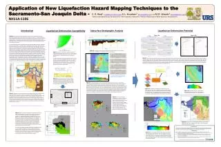
Coatings – Directional Boring. Tim Jenkins. Coatings – Directional Boring. Design Considerations (data collection) Contributed coating failures Pre-Operation steps Post-Operation steps. Design – Directional Boring Coatings. Data Collection for coating selection Surrounding Environment

E N D
Coatings – Directional Boring Tim Jenkins
Coatings – Directional Boring • Design Considerations (data collection) • Contributed coating failures • Pre-Operation steps • Post-Operation steps
Design – Directional Boring Coatings • Data Collection for coating selection • Surrounding Environment • Soil composite • Location • Foreign lines – • Other pipelines • AC Transmission towers • Timeframe
Design – Directional Boring Coatings • Powercrete – • 12 to 15 mils of FBE (Fusion bonded Epoxy) 3M 6233 • Concrete polymer base outer coat 20mils per application, two applications normally used • Typically 55 to 60 mils coating thickness • FBE – Dual coat • 12 to 15 mils of 3M 6233 • 20 mils of a Dual coat application of 3M 6352 • Typically 35 mils total coating thickness
Design – Directional Boring Coatings • Time frame considerations – • Powercrete – hand applied, 4 joints per 2 hours can be coated • FBE – Dual coat – assembly line, 3000 feet in three hours
Design – Directional Boring Coatings • Durability – • Powercrete – UV protected, more abrasive resistance in comparison to the FBE dual coat • Recommended practice – • Abrasive environment use the Powercrete application, • In well known normal soil application, FBE dual coat acceptable and probably more cost effective
Design – Directional Boring Coatings • Coatings Case history - Failures • The most popular coating failure - • Cathodic Shielding • Rock formation • Pipe wedge next to a rock formation at the point of coating holiday • Disbondment coating • Coating becomes disbondment from the surface of the pipe, but shields the CP from the surface of the metallic structure exposed under the coating
Cathodic Shielding - Rock CP CP ROCK Pipeline CP
Cathodic Shielding – Coating Disbondment CP Pipeline CP
Design – Directional Boring Coatings • Coatings Case history - Failures • Thickness of coating application – • The thicker of the coating, less durable, more brittle
Design – Directional Boring Coatings • Coatings Case history - Failures • Powercrete – • Flexibility – Degrees per pipe diameter • 1.4° for 35 mils • .75° for 55 mils • FBE – Dual Coat – • Flexibility – Degrees per pipe diameter • 2.8° for 35 mils
Design – Directional Boring Coatings • Coatings Case history – Failures • FBE Dual coat more flexible than Powercrete But,,, • Powercrete more impact resistance than FBE
Design – Directional Boring Coatings • Powercrete application adhesive bond to the FBE, and the dual coat 3M will result of complete pull out of coating application from the metal surface due to, coating flexibility angle being too great • In a normal pulling process, coating will be disbondment by layers and normally does not result in total removal
Design – Directional Boring Coatings • Girth Welds – • Two part Liquid Epoxy used • Protal 7200 - 50° or greater • Protal 7125 - 50° or less • R95 – Powercrete J (new) • Pipe Preparation – • Sand blasting – NACE 2 or SSPC-SP10
Design – Directional Boring Coatings • Transmission Class pipeline • ECDA • Pipe thickness design • %SYMS • ICDA • Internal Coupons • Probes • Inclination angle consideration • Do not get greater than the Critical Inclination angle • Inline Inspection – smart pigging
Pre-Operation Steps • Columbia Gas needs to inspect all coated pipe line at the coating mill before the pipe is coated • Corrosion Technicians are being trained, KTA certified • Communication should be placed to Corrosion FLL by Supply chain • Need to consider cost of technician or coating inspector to work order budget
Corrosion Department InspectingPowercrete application for Maumee River Crossing
Pre-Operation Steps • Pipe Inspected in the field by the corrosion department • Determine any coating defects due to shipment • Pipe and girth welds coatings inspected in the field by the corrosion technicians • Dew point readings • Pipe Temperature • Chloride check • DFT • WFT • Observe Jeeping process – recommend voltage setting
Post Operation Steps • Survey – Coating and CP • CP – • CIS – Close Interval survey • External Coupons used • Coating • DCVG – Direct Current Voltage Gradient • ACVG – PCM – Alternate Current Voltage Gradient • Cost of survey new steel pipe by corrosion department should be considered on the work order budget
Thank You Any Questions??