Download
1 / 24
280 likes | 559 Views
This chapter in the book includes: Objectives Study Guide 10.1 VHDL Description of Combinational Circuits 10.2 VHDL Models for Multiplexers 10.3 VHDL Modules 10.4 Signals and Constants 10.5 Arrays 10.6 VHDL Operators 10.7 Packages and Libraries 10.8 IEEE Standard Logic

E N D
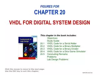
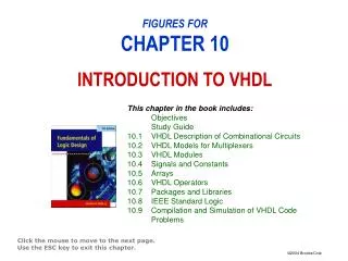
This chapter in the book includes: Objectives Study Guide 10.1 VHDL Description of Combinational Circuits 10.2 VHDL Models for Multiplexers 10.3 VHDL Modules 10.4 Signals and Constants 10.5 Arrays 10.6 VHDL Operators 10.7 Packages and Libraries 10.8 IEEE Standard Logic 10.9 Compilation and Simulation of VHDL Code Problems FIGURES FORCHAPTER 10INTRODUCTION TO VHDL Click the mouse to move to the next page. Use the ESC key to exit this chapter.
Figure 10-3: Three Gates with a Common Input and Different Delays
entity FullAdder isport (X,Y,Cin: in bit; --Inputs Cout, Sum: out bit); --Outputsend FullAdder; architecture Equations of FullAdder isbegin -- concurrent assignment statements Sum <= X xor Y xor Cin after 10 ns; Cout <= (X and Y) or (X and Cin) or (Y and Cin) after 10 ns; endEquations ; Figure 10-10: Full Adder Module
1 entity ROM9_17 is2 port (A, B, C: in bit; F: out bit_vector(0 to 3));3 endentity; 4 architecture ROM of ROM9_17 is5 type ROM8X4 is array (0 to 7) of bit_vector(0 to 3);6 constant ROM1: ROM8X4 := ("1010", "1010", "0111","0101", "1100", "0001", "1111", "0101");7 signal index: Integer range 0 to 7;8 begin9Index <= vec2int(A&B&C); -- A&B&C Is a 3-bit vector10 -- vec2int is a function that converts this vector to an integer11 F <= ROM1 (index);12 -- this statement reads the output from the ROM13 end ROM; Figure 10-13: VHDL Description of a ROM
Figure 10-15: NOR-NOR Circuit and Structural VHDL Code Using Library Components
entity IC_pin is port(IO_pin: inout std_logic); endentity; architecture bi_dir of IC_pin is component IC port(input: in std_logic; output: out std_logic); endcomponent; signal input, output, en: std_logic; begin -- connections to bi-directional I/O pin IO_pin <= output when en = '1' else 'Z'; input <= IO_pin; IC1: IC port map (input, output); end bi_dir; Figure 10-20: VHDL Code for Bi-Directional I/O Pin
Figure 10-21: Compilation, Simulation, and Synthesis of VHDL Code