Download

1 / 32
420 likes | 748 Views
GAS POWER CYCLES. Chapter 9. Introduction. Two important areas of application for thermodynamics are power generation and refrigeration . Both power generation and refrigeration are usually accomplished by a system that operates on a thermodynamics cycle.

E N D
GAS POWER CYCLES Chapter 9
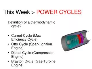
Introduction • Two important areas of application for thermodynamics are power generation and refrigeration. • Both power generation and refrigeration are usually accomplished by a system that operates on a thermodynamics cycle. • Thermodynamics cycles can be divided into two categories: • Power Cycles • Refrigeration Cycles
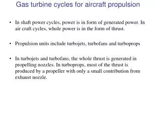
Introduction • Power cycles can be categorized as: • Gas power cycles • Vapor power cycle • Combined Power Cycles • In gas cycles, the working fluid remains in the gaseous phase throughout the entire cycle. • In vapor cycles the working fluid exists in a vapor phase during one part of the cycle and in a liquid phase during another part.
Basic Considerations • Closed cycle: the working fluid is returned to the initial state at the end of the cycle and is re-circulated. • Open cycle: the working fluid is renewed at the end of each cycle instead of being re-circulated. • Actual Cycle: The cycle encountered in actual devices are difficult to analyze. • Ideal Cycle: All the internal irreversibilities are neglected.
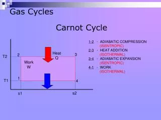
Carnot Cycle • The Carnot cycle is composed of 4 totally reversible processes: • Isothermal heat addition at high temperature (TH). • Isentropic expansion from high temperature to low temperature. • Isothermal heat rejection at low temperature (TL). • Isentropic compression from low temperature to high temperature.
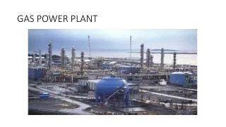
Gas Power Cycles • In gas power cycles, the working fluid remains a gas throughout the entire cycle. • Examples of devices that operate on gas power cycles: • Spark-Ignition Automobile Engines. • Diesel Engines. • Convectional Gas turbines.
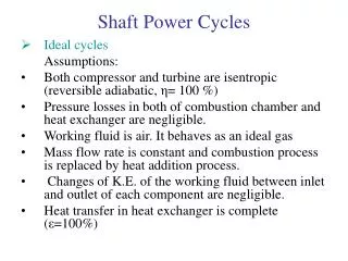
Air-Standard Assumptions • To simplify the analysis of actual gas cycles these assumptions are: • The working fluid is air and assumed to be an ideal gas. • All the processes are internally reversible. • The combustion process is replaced by a heat-addition process from an external source. • The exhaust process is replaced by a heat rejection process that restores the working fluid to its initial state.
Air-Standard Assumptions • Energy in the form of heat is provided by burning a fuel within the system boundaries.
Basic components The basic components are described by the following diagrams
Basic Components • Compression Ratio (r):The ratio of the maximum volume formed in the cylinder to the minimum (clearance) volume is called the compression ratio. • Mean Effective Pressure (MEP): It is a fictitious pressure that, if it acted on the piston during the entire power stroke, would produce the same amount of net work as that produced during the actual cycle.
Basic Components Note: • The mean effective pressure can be used as a parameter to compare the performances of reciprocating engines of equal size. • The engine with a larger value of MEP will deliver more net work per cycle and thus will perform better.
Classifications Reciprocating Engines are classified as: • Spark-ignition (SI) engine where: • The combustion of the air-fuel mixture is initiated by a spark plug. • Otto Cycle is the ideal cycle for the SI Engine. • Compression-ignition (CI) engine where: • The air-fuel mixture is self-ignited as a result of compressing the mixture above its self-ignition temperature. • Diesel Cycle is the ideal cycle for CI Engine.
Otto Cycle • The Otto cycle is the ideal cycle for SI engines. • In S I engines, the piston executes 4 complete strokes. • These engines are called 4 stroke internal combustion engines. • Initially, both the intake and the exhaust valves are closed and the piston is at its lowest position (BDC).
Otto Cycle • The four strokes are: • Compression Stroke. • Expansion or Power Stroke. • Exhaust Stroke. • Intake stroke.
IdealOtto Cycle It consists of 4 internally reversible processes: 1-2 Isentropic Compression 2-3 Constant volume heat addition 3-4 isentropic expansion 4-1 Constant volume heat rejection
Diesel Cycle Read about Diesel Cycle (Text)
Two –stroke engines • All the four functions described above are executed in just two strokes: The power stroke and the compression stroke. • The outward motion of the piston is used to slightly pressurize the air-fuel mixture in the crankcase. • The intake and exhaust valves are replaced by openings in the lower portion of the cylinder wall.
Two –stroke engines • During the latter part of the power stoke, the piston uncovers first the exhaust port allowing the exhaust gases to be partially expelled and then the intake port, allowing the fresh air-fuel mixture to rush in and drive most of the remaining exhaust gases out of the cylinder. • The fresh air-fuel mixture is then compressed as the piston moves upward during the compression stroke and is subsequently ignited by a spark plug. • The two stroke engines are generally less efficient than four strokeones.
EXAMPLE8—9 The Ideal Jet Propulsion Cycle A turbojet aircraft flies with a velocity of 850 ft/s at an altitude where the air is at 5 psia and —40 The compressor has a pressure ratio of 10, and the temperature of the gases at the turbine inlet is 2000T. Air enters the compressor at a rate of 100 Ibm/s. Utilizing the cold-air-standard assumptions, determine (a) the temperature and pressure of the gases at the turbine exit, (b) the velocity of the gases at the nozzle exit, and (C) the propulsive efficiency of the cycle.