Download
1 / 27
270 likes | 433 Views
Multiplexing. SONET/SDH. Frequency Division Multiplexing; Wavelength Division Multiplexing; Time Division Multiplexing SONET/SDH. Multiplexing.

E N D
Multiplexing. SONET/SDH Frequency Division Multiplexing; Wavelength Division Multiplexing; Time Division Multiplexing SONET/SDH
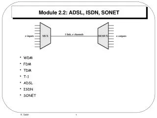
Multiplexing • For a telephone system it costs essentially the same amount of money to install and maintain a high-bandwidth trunk as a low-bandwidth trunk between two switching offices (i.e., the costs come from digging the trench) • So telephone companies have developed schemes for multiplexing many conversations over a single physical trunk • Two basic categories: FDM (Frequency Division Multiplexing) and TDM (Time Division Multiplexing)
Multiplexing • FDM - the frequency spectrum is divided into frequency bands, with each user having exclusive possession of some band • TDM - the users take turns (in a round-robin fashion), each one periodically getting the entire bandwidth for a little burst of time • FDM can be applied to fiber optics and is called WDM (wavelength division multiplexing)
Frequency Division Multiplexing • Example - three voice-grade telephone channels are multiplexed using FDM • Filters limit the usable bandwidth to about 3100 Hz per voice-grade channel • When many channels are multiplexed together, 4000 Hz is allocated to each channel to keep them well separated • First the voice channels are raised in frequency, each by a different amount • Then they can be combined as no two channels now occupy the same portion of the spectrum • There are gaps between the channels, but there is some overlap between adjacent channels because the filters do not have sharp edges
Frequency Division Multiplexing (a) The original bandwidths. (b) The bandwidths raised in frequency. (b) The multiplexed channel.
Frequency Division Multiplexing • Twelve 4000-Hz voice channels multiplexed into the 60 to 108 kHz band form a group • 12-kHz to 60-kHz band is sometimes used for another group • Five groups (60 voice channels) can be multiplexed to form a supergroup • The next unit is the mastergroup, which is five supergroups(CCITT standard) or ten supergroups (Bell system)
Wavelength Division Multiplexing • For fiber optic channels, a variation of frequency division multiplexing is used - WDM (Wavelength Division Multiplexing) • In the next slide, four fibers come together at an optical combiner, each with its energy present at a different wavelength • The four beams are combined onto a single shared fiber for transmission to a distant destination • At the far end, the beam is split up over as many fibers as there were on the input side • Each output fiber contains a short, specially-constructed core that filters out all but one wavelength
Wavelength Division Multiplexing Wavelength division multiplexing.
Wavelength Division Multiplexing • Similar to frequency division multiplexing at very high frequencies • The only difference with electrical FDM is that an optical system using a diffraction grating is completely passive and thus highly reliable • When the number of channels is very large and the wavelengths are spaced close together, for example, 0.1 nm, the system is often referred to as DWDM (Dense WDM)
Wavelength Division Multiplexing • Each wavelength (color) is a independent channel running at data rate at 2.5Gbit/s, 10Gbit/s, 40Gbit/s or even 100Gbit/s (under development) • Fibers carrying 64 and more channels (wavelengths) are already available on the market now - can run 2,560 Gbit/s data rate on a single fiber • If there are 48 fibers in a single fiber optic cable it gives us an amazing 2,560 Gbit/s x 48 = 122,880 Gbit/s link (3500 full length movies/sec) • This kind of high speed and high fiber count links are usually only deployed for Internet backbones
Wavelength Division Multiplexing • There has been an improvement on optical amplifiers • In the past, on every 100 km it was necessary to split up all the channels and convert each one to an electrical signal for amplification separately before reconverting to optical and combining them • Nowadays, all optical amplifiers can regenerate the entire signal once every 1000 km without the need for multiple opto-electrical conversions • It is also possible to build WDM systems that are switched - in such a device, the output filters are tunable using Fabry-Perot or Mach-Zehnder interferometers
Time Division Multiplexing • Although FDM is still used over copper wires or microwave channels, it requires analog circuitry • In contrast, TDM can be handled entirely by digital electronics, so it has become far more widespread in recent years • (-) it can only be used for digital data • But local loops produce analog signals, so a conversion is needed from analog to digital in the end office, where all the individual local loops come together to be combined onto outgoing trunks
Time Division Multiplexing • How multiple analog voice signals are digitized and combined onto a single outgoing digital trunk? • Computer data sent over a modem are also analog – these signals are digitized in the end office by a device called a codec (coder-decoder), producing a series of 8-bit numbers • The codec makes 8000 samples per second (125 µsec/sample) and this is called PCM (Pulse Code Modulation) • (Nyquist theorem says that this is sufficient to capture all the information from the 4-kHz telephone channel bandwidth - at a lower sampling rate, information would be lost; at a higher one, no extra information would be gained) • PCM forms the heart of the modern telephone system – due to it all time intervals within the telephone system are multiples of 125 µsec.
T1 carrier • In the past, CCITT was unable to reach agreement on an international standard for PCM, so a variety of incompatible schemes are now in use in different countries around the world • The method used in North America and Japan is the T1 carrier - consists of 24 voice channels multiplexed together • Each of the 24 channels, in turn, gets to insert 8 bits into the output stream. Seven bits are data and one is for control, yielding 7 x 8000 = 56,000 bps of data, and 1 x 8000 = 8000 bps of signaling information per channel
Time Division Multiplexing The T1 carrier (1.544 Mbps).
T1 carrier • A frame consists of 24 x 8 = 192 bits plus one extra bit for framing, yielding 193 bits every 125 µsec = gross data rate of 1.544 Mbps • The 193rd bit is used for frame synchronization - the pattern 0101010101 . . . . (alternating for each new frame) • Normally, the receiver keeps checking this bit to make sure that it has not lost synchronization • When a T1 system is being used entirely for data, only 23 of the channels are used for data. The 24th one is used for a special synchronization pattern, to allow faster recovery in the event that the frame slips
E1 carrier • A PCM carrier at 2.048 Mbps is called E1 • This carrier has 32 8-bit data samples packed into the basic 125-µsec frame • Thirty of the channels are used for information and two are used for signaling - the time slot 0 is devoted to transmission management and time slot 16 for signaling; the rest were assigned originally for voice/data transport • Outside North America and Japan, the 2.048-Mbps E1 carrier is used instead of T1
Reducing number of bits per channel • Ways to reduce the number of bits needed per channel - appropriate not only for encoding speech, but for the digitization of any analog signal • The compaction methods are based on the principle that the signal changes relatively slowly compared to the sampling frequency, so that much of the information in the 7- or 8-bit digital level is redundant
Reducing number of bits per channel • 1) differential pulse code modulation - outputs not the digitized amplitude, but the difference between the current value and the previous one • Jumps of ±16 or more on a scale of 128 are unlikely, 5 bits should suffice instead of 7 - if the signal does occasionally jump wildly, the encoding logic may require several sampling periods to ''catch up.'' For speech, the error introduced can be ignored
Reducing number of bits per channel • A variation of this compaction method requires each sampled value to differ from its predecessor by either +1 or -1. Under these conditions, a single bit can be transmitted, telling whether the new sample is above or below the previous one. This technique, called delta modulation, is illustrated in the next slide • Like all compaction techniques that assume small level changes between consecutive samples, delta encoding can get into trouble if the signal changes too fast - when this happens, information is lost
Time Division Multiplexing Delta modulation.
Multiplexing multiple T1 carriers • Time division multiplexing allows multiple T1 carriers to be multiplexed into higher-order carriers • In the slide (on the left) four T1 channels are multiplexed onto one T2 channel • The multiplexing at T2 and above is done bit for bit, rather than byte for byte with the 24 voice channels that make up a T1 frame • Four T1 streams at 1.544 Mbps should generate 6.176 Mbps, but T2 is actually 6.312 Mbps - the extra bits are used for framing and recovery in case the carrier slips • T1 and T3 are widely used by customers, whereas T2 and T4 are only used within the telephone system itself, so they are not well known
Time Division Multiplexing Multiplexing T1 streams into higher carriers.
Multiplexing multiple T1 carriers • At the next level, seven T2 streams are combined bitwise to form a T3 stream • Six T3 streams are joined to form a T4 stream • At each step a small amount of overhead is added for framing and recovery in case the synchronization between sender and receiver is lost • The CCITT hierarchy for 32, 128, 512, 2048, and 8192 channels runs at speeds of 2.048, 8.848, 34.304, 139.264, and 565.148 Mbps
SONET/SDH – standards for optical systems • SONET (Synchronous Optical NETwork) – US standard for optical TDM system for telephone traffic • CCITT recommendations - SDH (Synchronous Digital Hierarchy) differ from SONET only in minor ways • Virtually all the long-distance telephone traffic in the United States, and much of it elsewhere, now uses trunks running SONET in the physical layer
SONET/SDH • SONET a traditional TDM system, with the entire bandwidth of the fiber devoted to one channel containing time slots for the various subchannels • SONET is a synchronous system - it is controlled by a master clock with an accuracy of about 1 part in 109 • Bits on a SONET line are sent out at extremely precise intervals, controlled by the master clock • the sender and receiver are tied to a common clock