Download
1 / 1
10 likes | 137 Views
A novel concept for measuring seawater inherent optical properties in and out of the water. Alina Gainusa Bogdan and Emmanuel Boss School of Marine Sciences, University of Maine, Orono, ME, 04469, US . Intensity Geometry. Scattering Absorption.

E N D
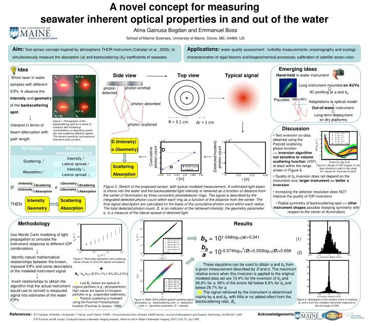
A novel concept for measuring seawater inherent optical properties in and out of the water Alina Gainusa Bogdan and Emmanuel Boss School of Marine Sciences, University of Maine, Orono, ME, 04469, US Intensity Geometry Scattering Absorption Aim:Test sensor concept inspired by atmospheric THOR instrument (Cahalan et al., 2005), to simultaneously measure the absorption (a) and backscattering (bb) coefficients of seawater. Applications:water quality assessment - turbidity measurements; oceanography and ecology - characterization of algal blooms and biogeochemical processes; calibration of satellite ocean color. Emerging ideas Top view Typical signal Side view Hand-held in-water instrument Idea Shine laser in water samples with different IOPs observe the intensity and geometry of the backscattering spot. Long instrument mounted on AUVs a0 b0 a1 • b1> b0 • a2> a1 b1 • a1> a0 b0 3D profiling of a and bb photon emitted photon detected Adaptations to optical model Plausible: Out-of-water instrument photon absorbed Long-term deployment on dry platforms R = 3.1 cm Δr = 1 cm photon scattered Discussion Figure 1. Photographs of the backscattering spot for a series of solutions with increasing concentrations of absorbing (green die) and scattering (Maalox) agents. The camera sensitivity and exposure time were held constant. Interpret in terms of beam attenuation with path length. • Test inversion on data • obtained using the • Petzold scattering • phase function • => inversion algorithm • not sensitive to volume • scattering function (VSF), • at least within the range • shown in Figure 6. • Quality of bb inversion does not depend on the instrument size; larger instrument => better a inversion • Increasing the detector resolution does NOT improve the quality of IOP inversions • Radial symmetry of backscattering spot => other instrument shapes possible (keeping symmetry with respect to the center of illumination) D Cumulative photon count (Detected/incident) photon count Figure 6. Range of VSF shapes (in the back direction) used in this study. ‘FF’ stands for ‘Fournier-Forand’. α r [m] r [m] Scattering Absorption dIntensity/dScattering dGeometry/dScattering Figure 3. Sketch of the proposed sensor, with typical modeled measurement. A collimated light beam is shone into the water and the backscattered light intensity is retrieved as a function of distance from the center of illumination by three concentric photodetector rings. The signal is described by the integrated detected photon count within each ring as a function of the distance from the center. The final signal descriptors are calculated on the basis of the cumulative photon count within each radius. The total detected photon count, D, is an indicator of the retrieved intensity; the geometry parameter, α, is a measure of the lateral spread of detected light. IF ≠ dGeometry/dAbsorption dIntensity/dAbsorption D (Intensity) α (Geometry) THEN Methodology Use Monte Carlo modeling of light propagation to simulate the instrument response to different IOP combinations Results bb = 101.048log10(α)+0.341(1) Identify robust mathematical relationships between the known, imposed IOPs and some descriptors of the modeled instrument signal Figure 2. Particulate absorption and scattering values chosen to drive the optical simulations. bb These equations can be used to obtain a and bb from a given measurement described by D and α. The maximum relative errors when this inversion is applied to the original modeled data set are 13.4% for the inversion of bb and 56.9% for a. 90% of the errors fall below 6.9% for bb and below 29.7% for a. The signal retrieved by the instrument is determined mainly by a and bb, with little or no added effect from the backscattering ratio, Bp. + = 10-0.074log102(D)+0.353log10(D)+0.656(2) a Invert relationships to obtain the algorithm that the actual instrument would use to convert a measured signal into estimates of the water IOPs Bp≡bbp/bp= [0.5%,1%,1.5%,2%,2.5%] Low Bp values are typical of organic particles (e.g., phytoplankton); high values are typical of inorganic particles (e.g., suspended sediments). Particle scattering is modeled using the Fournier-Forand phase function (Fournier & Jonasz, 1999) Figure 4. Water IOPs plotted against resulting signal descriptors. bb - backscattering coef.; a - absorption coef.; α - geometry parameter.; D - intensity. Figure 5. Histograms of the relative errors in inverting bb and a from the modeled instrument response to the full range of IOPs References:R F Cahalan, M McGill, J Kolasinski, T Várnai, and K Yetzer. THOR – Cloud thickness from off beam LIDAR returns. Journal of Atmospheric and Oceanic Technology, 22:605-627, 2005 G R Fournier and M Jonasz. Computer-based underwater imaging analysis. Airborne and In-Water Underwater Imaging, 3761(1):62-70, July 1999 Acknowledgements: