Download

1 / 15
150 likes | 268 Views
Concurrent statements. S. Cout. Cin. +. B. A. We’ve discussed the concurrent signal assignment: S <= A xor B xor Cin; Cout <= (A and B) or (A and Cin) or (B and Cin);

E N D
S Cout Cin + B A We’ve discussed the concurrent signal assignment: S <= A xor B xor Cin; Cout <= (A and B) or (A and Cin) or (B and Cin); The forms for signal S and Cout are known. What if these forms are not known? What if all we know is the truth table? In VHDL a function can be specified directly using the “selected signal assignment “ statement.
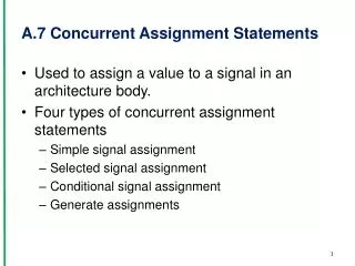
Selected signal assignment: Similar to switch …. case …. case ….in C. Syntax: withselect_expressionselect target_signal <= expression1whenchoice_list1, expression2whenchoice_list2, • • • expressionN–1whenchoice_listN–1, expressionN whenchoice_listN; • The select_expressionvalue must be of a discrete type or of a one-dimensional array type. • Target_signalcan be scalar or composite. • Based on the value of the select_expression that matches the choice value specified in a list, the value (or values) of the corresponding expression is assigned to the target signal. • A particular choice is specified no more than once in all lists.
withselect_expressionselect target_signal <= expression1whenchoice_list1, expression2whenchoice_list2, • • • expressionN–1whenchoice_listN–1, expressionN whenchoice_listN; • The choice_list may be made of a single value of the select_expression, logical "or" of several values or may be specified as a range of values. • All possible values of the select expression must be covered by the choices. • Values not covered explicitly may be covered by an "others" choice, which covers all such values. The "others" choice, if used, must appear in the last position, instead of the choice_listN.
S Cout Cin + B A --VHDL description 3 Entity full_adder is Port ( iA, iB, iCin : in std_logic; oS, oCout : out std_logic ); end; architecture a of full_adder is signal saTmp : std_logic_vector (2 downto 0); begin saTmp <= iCin & B & A; -- 2 1 0 with saTmp select oS <= ‘0’ when “000”, ‘1’ when “001”, ‘1’ when “010”, ‘0’ when “011”, ‘1’ when “100”, ‘0’ when “101”, ‘0’ when “110”, ‘1’ whenothers; -- S <= A xor B xor Cin was simpler!!!
with saTmp select oCout<= ‘0’ when “000”, ‘0’ when “001”, ‘0’ when “010”, ‘1’ when “011”, ‘0’ when “100”, ‘1’ when “101”, ‘1’ when “110”, ‘1’ whenothers; End; -- arch a The description is too long! Much longer than the previous one! Let’s use choice lists! with saTmp select oCout<= ‘0’ when “000”|“001”|“010”|“100”, ‘1’ whenothers; oS <= ‘0’ when “000”|“011”|“101”|“110”, ‘1’ whenothers; Shorter, but somehow cofusing Let’s use a single assignment!
architecture a of full_adder is signal saTmp : std_logic_vector (2 downto 0); signal saCo_S : std_logic_vector (1 downto 0); -- 1 0 begin saTmp <= iCin & B & A; with saTmp select saCo_S <= “00” when “000”, “01” when “001”, “01” when “010”, “10” when “011”, “01” when “100”, “10” when “101”, “10” when “110”, “11” whenothers; oS <= saCo_S(0); oCout <= saCo_S(1); End;
Shorter description with choice lists! architecture a of eladder is signal saTmp : std_logic_vector (2 downto 0); signal saCo_S : std_logic_vector (1 downto 0); begin saTmp <= iCin & B & A; with saTmp select saCo_S <= “00” when “000”, “01” when “001”|“010”|“100”, “10” when “011”|“101”|“110”, “11” whenothers; oS <= saCo_S(0); oCout <= saCo_S(1); End;
Even Shorter with a qualified expression! architecture a of eladder is signal saTmp : std_logic_vector (2 downto 0); signal saCo_S : std_logic_vector (1 downto 0); begin saTmp <= iCin & B & A; with saTmp select saCo_S <= “00” when “000”, “01” when “001”|“010”|“100”, “10” when “011”|“101”|“110”, “11” whenothers; oS <= saCo_S(0); oCout <= saCo_S(1); End; Error! withiCin & B & Aselect withstd_logic_vector’(iCin & B & A)select
Consider a Hex to 7-segment decoder. The input is encoded on 4 bits and the output consist on 7 bits, one for each segment. The functionality of the decoder is specified through the following truth table: I3 I2I1I0g f e d c b a 0 0 0 0 1 0 0 0 0 0 0 0 0 0 1 1 1 1 1 0 0 1 ………… 1 1 1 1 0 0 0 1 1 1 0 The manual implementation requires the minimization of 7 boolean function of 4 variables each. A lot of work! But in VHDL……..
-- 7 segment decoder signal saHex : std_logic_vector(3 downto 0); signal saDLED : std_logic_vector (6 downto 0); …… with saHEX SELect -- gfedcba saDLED <= "1000000" when “0000”; --0 "1111001" when x“1", --1 "0100100" when x“2", --2 "0110000" when "0011", --3 "0011001" when "0100", --4 "0010010" when "0101", --5 "0000010" when "0110", --6 "1111000" when "0111", --7 "0000000" when "1000", --8 "0010000" when "1001", --9 "0001000" when "1010", --A "0000011" when "1011", --b "1000110" when "1100", --C "0100001" when "1101", --d "0000110" when "1110", --E "0001110" whenothers; --F
In the previous example the expressions consisted of constant values → truth table description In the next example each expression consists of a single signal → MUX description Entity Mux4 is Port ( iA,iB,iC,iD : in std_logic; iaS : in std_logic_vector (1 downto 0); oY : out std_logic ); end; architecture a of Mux4 is begin with iaS select oY <= iA when “00”, iB when “01”, iC when “10”, iD whenothers; end;
Usually a MUX has an Enable input. When Enable input is ‘0’, the output is unconditionally ‘0’: Entity Mux4_E is Port ( iA,iB,iC,iD : in std_logic; iaS : in std_logic_vector (1 downto 0); iE : in std_logic; oY : out std_logic ); end; architecture a of Mux4 is begin with iaS select oY <= iA when “00”, iB when “01”, iC when “10”, iD whenothers; oY <= oY and iE; -- Legal sequential code! -- An error in VHDL! (In fact, 2 errors!) -- Multiple drivers and output read! end;
How it should be implemented: Entity Mux4_E is Port ( iA,iB,iC,iD : in std_logic; iaS : in std_logic_vector (1 downto 0); iE : in std_logic; oY : out std_logic ); end; architecture a of Mux4 is signal sMO : std_logic; begin with iaS select sMO <= iA when “00”, iB when “01”, iC when “10”, iD whenothers; oY <= sMOand iE; end; A VHDL description is equivalent with a graph, not with a sequential program!
In the previous examples the expressions consisted of constant values or single signals. Let’s have an example with real expressions! Entity ALU is Port ( iaOP1,iaOP2 : in std_logic_vector (31 downto 0); iaCode : in std_logic_vector (1 downto 0); oaY : out std_logic_vector (31 downto 0); ); end; architecture a of ALU is Begin with iaCode select oaY <= iaOp1+iaOP2 when “00”, iaOp1-iaOP2 when “01”, iaOp1 and iaOP2 when “10”, iaOp1 or iaOP2 whenothers; end; Done!