Download
1 / 32
550 likes | 1.33k Views
Ceramic Matrix Composites In Design. Lance L Snead. Conventional Matrix Processes for SiC/SiC. Chemical vapor infiltration (CVI) makes a good reference material Stoichiometric & crystalline matrix Very good interface (interphase) control

E N D
Ceramic Matrix CompositesIn Design Lance L Snead
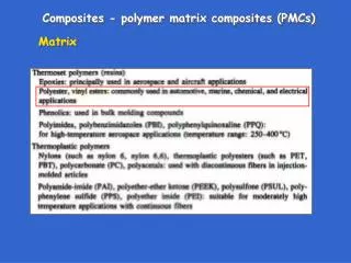
Conventional Matrix Processes for SiC/SiC • Chemical vapor infiltration (CVI) makes a good reference material • Stoichiometric & crystalline matrix • Very good interface (interphase) control • Alternate matrix processes need a lot more developmental work to be considered for fusion-grade materials • Melt-infiltration (MI, RS, LSI, MSI, …) • Unreacted Si imposes creep and chemical instability issues • Dual-phase SiC/Si matrix may cause severe irradiation damage • Polymer impregnation and pyrolysis (PIP) • Microporous nono-crystalline matrix results in very poor thermal conductivity • Non-stoichiometric nano-crystalline matrix causes severe irradiation damage
Fundamental Issues with Design • Currently there is a lack of uniform design methodology for structural design with ceramic composites. - ASTM procedures are lacking - ASME approval ~ 10 years following ASTM data-basing - Prototyping or design-code? • Composite properties are intrinsically anisotropic and unique to composite system. • QA of composites requires attention. • At present there have been no application of SiC composites in nuclear systems. They have had only limited application as structural material in non-nuclear systems.
First Nuclear Application? Gen IV Articulated Composite Control Rod Segment Control Rod Tube Architecture ± 45° braid (for SiC variant) SiC/SiC : Nicalon Type S Fiber / CVI SiC Matrix
Reference NGNP-Grade SiC/SiC Manufactured by Hypertherm, Inc Nicalon Type-S, Multilayer SiC Interphase ICVI SiC Matrix Density: ~2.9 g/cm3 Porosity: ~7% Fiber volume fraction: ~40% 20mm SiC matrix SiC/PyC multilayer 300mm PyC 1mm Hi-Nicalon Type-S fiber
Joining Technology Integration for NITE-SiC/SiC Kohyama (a) NITE-process Joining (b) Mechanical Joining Kyoto University
Matrix Cracking Model E. Vagaggini, et al., J. Am. Ceram. Soc. 78 (1995) 2709-2720. Definition of Key Tensile Parameters – PLS • Proportional Limit Stress (PLS) • =Matrix Cracking Stress (smc) • Transition stress from elastic to quasi-ductile fracture. • Depends on Young’s moduli of fiber, matrix and composites, interfacial friction stress, matrix fracture energy and misfit stress. UTS × PLS E E. Vagaggini, et al., J. Am. Ceram. Soc. 78 (1995) 2709-2720.
Tensile Strength Model W.A. Curtin, J. Am. Ceram. Soc. 74 (1991) 2837-2845. Definition of Key Tensile Parameters – Tensile Strength • Ultimate Tensile Strength (UTS) • =Fracture strength • Closely dependent on fiber strength and fiber volume fraction. UTS × PLS E E. Vagaggini, et al., J. Am. Ceram. Soc. 78 (1995) 2709-2720.
Evaluation on Damage Accumulation • Matrix Crack Saturation Stress (ss) • End of progressive matrix cracking. • Beyond this stress, composite strength simply depends on fiber strength. • Magnitude of matrix cracks can be estimated by damage parameter. • Damage Parameter (D) • Defined by elastic unloading (E*). • No damage when D=0. • Maximum Loop Width (demax) • Enlarged hysteresis loop width implies the lower sliding stress (tf) and/or higher crack density (d). UTS × Matrix Crack Saturation Stress (ss) Maximum Loop Width (demax) Elastic Unloading (E*) E. Vagaggini, et al., J. Am. Ceram. Soc. 78 (1995) 2709.
Stress Criterions in Composite Failure sx s22 Longitudinal fiber direction Tensile loading direction q s11 t12 1) s11 > smc(= a critical stress to initiate transverse cracking, i.e., matrix cracking) 2) s22 > sdetach (= a critical stress to initiate tunneling cracking by fiber detachment) 3) t12 > tshear (= a critical stress to initiate tunneling cracking by in-plane shear)
Axial and Off-axis Tensile Fracture Behavior S/W-[0º/90º] S/W-[±45º] *Straight bar specimen: 20L x 4W x 2.5T mm3 • PLS (= first matrix cracking stress) is recognized as a critical limit stress for the component design.
First Matrix Cracking vs. Transverse Matrix Cracking ◆S/W-0/90 ◆S/W-45 ◆S/W-0/90 ◆S/W-45 ◆S/W-0/90 ◆S/W-45 smc sPLS smc smc • Proportional limit tensile stress (first matrix cracking stress) indicates an initiation of microcracks in CMCs. The PLS of 2D CMCs is identical to a stress to initiate tunneling cracking in off-axis bundles. • Secondary damage accumulation by transverse matrix cracking in the axial fiber bundles.
Typical Properties of Orthogonal 2D CVI SiC/SiC Composites (RT - ~1200ºC)
Anisotropy of Proportional Limit Stress Vf = 0.3~0.4, uni- or bi-axial CVI composites Transverse matrix cracking stress (smc) of unidirectional CMCs. cf.) smc of 2D composites would be much lower. ◇ Braid, ◆ Braid △ S/W, ▲ UD □ P/W, ■ S/W Proportional limit in-plane shear stress, which depends significantly on the fiber volume fraction normal to the fracture plane. Tunneling crack initiation stress of [0º/90º] CMCs.
Ceramic matrix composites, in the absence of environmental effects, will endure very long periods of service at stress below the point of matrix microcracking. Above matrix microcracking thermal conductivity and static and fatigue mechanical properties begin to degrade. Design should be based on operating stress below the matrix microcraking (or alternate failure mode) with an appropriate safety factor. Given the Weibull nature of CMC failure this safety factor should be generous. Design Stress < 0.5 mcor < 0.5 ILS Design Basis Accident< 0.75 u ? Design Stress Criteria
Fracture Behavior of Composites and Irradiation • Reinforcing fibers are the structural backbone. • Fiber/matrix interface plays an important role. • Composite performance is determined by various constitute properties.
Radiation-induced electrical conductivity in SiC 7000 ohm-cm
Typical Properties for 2D SiC/SiC ITER TBM Flow Channel Insert Applications *No data available; very rough estimate.
z y x Young’s Modulus of Composites – Rule of Mixtures E: Young’s modulus n: Poisson’s ratio V: volume fraction k: transverse bulk modulus G: transverse shear modulus Hi-Nicalon Type-S / CVI-SiC 10% uncertainty Subscripts 1: embedded material 2: surrounding material Superscripts A: axial T: transverse 1.8dpa 380C 1.0, 7.7dpa 800C 1.0dpa 800C 1.0dpa 1000C 7.7dpa 800C 1.0dpa 800C 1.0dpa 1000C Open symbols indicate non-irradiated specimens 1.0dpa 1000C • Transversely isotropic composite system. • Fibers with carbon coating embedded in matrix. • Matrix is assumed to have columnar pores, which are homogeneously distributed along the fiber bundles. Z. Hashin, J. Appl. Phys.46 (1979) 543-550.
z y x Strength of Composites – Rule of Mixtures E: Young’s modulus n: Poisson’s ratio V: volume fraction k: transverse bulk modulus G: transverse shear modulus Stress Subscripts 1: embedded material 2: surrounding material Superscripts A: axial T: transverse Strain .
Neutron Dose Dependent of Interfacial Shear Strength: Implications from Model Analysis Hi-Nicalon Type-S / CVI-SiC • Interfacial debond shear strength (IDSS) and interfacial friction stress (IFS) probably have a peak around the neutron dose level of 1 dpa, i.e., “turn around”. • “Turn-around” of the shear properties are due primary to the differential swelling induced residual stress at the interface. • Swelling behavior of PyC, which depends strongly on fast neutron fluence, has a significant influence on the “turn-around” behavior. • Irradiation creep may relieve residual stresses at the interface, reducing the gap in the actual case.
Irradiation Effect on Proportional Limit Stress (PLS) • Irradiation effect on PLS is very complicated issue • Elastic moduli of fiber, matrix and composites are almost unchanged or slightly decreased. • Matrix fracture energy may increase at higher temperature irradiation. • Interfacial friction stress may change depending on neutron dose. • Probably have relaxation of misfit stress by irradiation creep. UD Hi-Nicalon Type-S / CVI-SiC Non-irradiated
m = 6.0 s = 3.2 +/-0.6 m = 4.6 s = 3.3 +/-0.8 m = 4.3 s = 3.2 +/-0.8 m = 4.8 s = 3.2 +/-0.7 Irradiation Effect on Fiber Strength • No significant deterioration was reported for Hi-Nicalon Type-S SiC fiber up to 7.7 dpa over the wide temperature range of 300~800ºC. T. Nozawa, et al., J. Nucl. Mater. 329-333 (2004) 544-548.
Survival Strength of Various SiC/SiC Composites under Neutron Irradiation UD Hi-Nicalon Type-S / CVI-SiC PyC Multilayer Non-irradiated
Irradiation Effect on Damage Accumulation • Non-irradiated composites failed before the matrix crack saturation. • Irradiated composites showed lower proportional limit tensile stress. • Higher crack density and reduction of interfacial friction give larger loop width upon irradiation. • “Progressive matrix cracking regime” for irradiated composites with the matrix crack saturation. • Increased tensile strength and strain to failure by neutron irradiation. UD Hi-Nicalon Type-S / 720nm PyC / CVI-SiC Non-irradiated 7.7dpa, 800ºC Y. Katoh, et al., submitted to J. Nucl. Mater.
Young’s modulus of CVD SiC Definition of Key Tensile Parameters – Young’s Modulus • Young’s Modulus (E) = Initial tangent modulus • Depends on fiber volume fraction and porosity. • Irradiation-induced dimensional change may influence Young’s moduli of the constituents. UTS × PLS E E. Vagaggini, et al., J. Am. Ceram. Soc. 78 (1995) 2709-2720.
Intermediate Quality Irradiated Graphite (Causey, Snead) 1000 High Quality Irradiated CFC (Causey, Snead) 100 T-3 Retention (appm) Non-irradiated, infinite charge time 10 Non-Irradiated 1 hr Charge Time 1 200 400 600 800 1000 1200 1400 Irradiation / T-3 Loading Temperature (C) • T-3 attaches to basal plane edges and highly defected structure. More perfect material and/or high temperature allows less retention. NRL IFE 2/2001