Download
1 / 22
230 likes | 349 Views
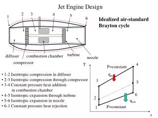
EM PROPAGATION IN JET ENGINE TURBINES. Eric Walton, Jonathan Young, Jim Moore and Kyle Davis The Ohio State University ElectroScience Laboratory 2006 AMTA Meeting; Austin TX. EM PROPAGATION IN JET ENGINE TURBINES. EM PROPAGATION IN JET ENGINE TURBINES. Small Turbine (F16)

E N D
EM PROPAGATIONIN JET ENGINE TURBINES Eric Walton, Jonathan Young, Jim Moore and Kyle Davis The Ohio State University ElectroScience Laboratory 2006 AMTA Meeting; Austin TX.
EM PROPAGATION IN JET ENGINE TURBINES Small Turbine (F16) (compressor stage only) “B” = INLET TO COMPRESSOR (on the bottom in this photo) “A” = OUTLET FROM COMPRESSOR (on top in photo) Large Turbine [“F-110-GE-100”] (747) Borehole locations
Circumfer’l Polarization A-to-bottom borehole transmission (circumferential polariz. 90° increments) F16 TURBINE FREE-SPACE (same dist) OTHER DATA SHOWS SIMILAR RIPPLE PATTERN. FROM PREVIOUS SLIDE, THERE IS ONLY 45 CM RANGE SPREAD (1.5 NS), WHILE THESE DATA ARE SHOWING APPROX. 5 NS SPREAD
EM PROPAGATION IN JET ENGINE TURBINES Free space Noise level 747 Turbine (inlet to stage 1 borehole) TIME (NS)
EM PROPAGATION IN JET ENGINE TURBINES Free space window Amp. (dB) vs. Freq.; F110 Outlet to Inlet; Circumf. Polarization; Various Blade Rotation Angles
EM PROPAGATION IN JET ENGINE TURBINES window Amp. (dB) vs. Freq.; F110 Outlet to Inlet Radial Polarization; Various Blade Rotation Angles
EM PROPAGATION IN JET ENGINE TURBINES Ring Down = 20 ns Amp. (dB) vs. Time (ns); F110; Outlet To Inlet Radial Polarization; Various Blade Rotation Angles
EM PROPAGATION IN JET ENGINE TURBINES • TEST MATRIX • (I CAN’T SHOW ALL OF IT IN THE TIME ALLOTTED) • F16 AND 707 TURBINES • RADIAL AND CIRCUMFERENTIAL POLARIZATION • 2 TO 20 GHZ • A SMALL ROTATIONAL SECTOR WITH SMALL INCREMENTS • THROUGH ENTIRE COMPRESSOR SECTION • TO/BETWEEN VARIOUS BOREHOLE COMBINATIONS • 0-90-180-270 ANGULAR SETS • CALIBRATION TO FREE SPACE PROPAGATION (SAME DISTANCE)
EM PROPAGATION IN JET ENGINE TURBINES • • Signal loss is often less than in free space. (confined?) • There is no “main bang,” (no large initial time domain term) • signal spread out in time so initial direct term is as small as the multiple reflection terms. • • The multiple reflection terms spread out over a duration that corresponds to more than 3 times the physical size of the turbine. • • In the time domain • individual stages can be discerned • but not individual turbine blades • this indicates that the internal propagation • is axial • with multiple reflections • but not circumferential or spiral.
EM “WINDOWS” IN JET ENGINE TURBINES No variation with rotation! WINDOWS Amp. (dB) vs. Freq. and Rotation; F110-GE-100 (Boeing 747) Propagation to Farthest Borehole (Circumf. Polariz) vs. Freq. and Rotor Position.
EM PROPAGATION IN JET ENGINE TURBINES No variation with rotation!
EM MODEL OF TURBINE PROPAGATION MODEL THE PROPAGATION INSIDE A TURBINE AS A SIGNAL TRANSMITTER AND A SIGNAL RECEIVER WITH A SET OF “POINT” SCATTERERS IN BETWEEN. (A “POINT SCATTERER” IS A POINT IN SPACE WHERE THE SCATTERING IS CENTERED. THE SCATTERER HAS NO FREQUENCY, ANGLE, OR POLARIZATION DEPENDENCE.) Rx Tx R S R S R S R
EM PROPAGATION IN JET ENGINE TURBINES CONSIDER A SINGLE DOMINANT SCATTER (THIS SHOULD PRODUCE A SINGLE MODE INTERFERENCE PATTERN) DATA FILE “Direct_one.txt” one direct path and one main scatter As Zs Rs Ts Ar Zr Rr Tr 1 0 28 0 1 34 18 0 .9 25 22 30 .01 27 23 45 WE EXPECT THIS BEHAVIOR ! AMP (DB) 2.0 FREQ (GHZ) 20.0 SINGLE MODE PATTERN (NOTE PERIODICITY IS AS EXPECTED)
EM PROPAGATION IN JET ENGINE TURBINES NOW LETS GET MORE COMPLEX: Rx Tx PARTIAL F16 GEOMETRY WITH FLOOR BOUNCE INCLUDED (SORT OF) NOTE MULTIPLE BLADES/SCATTERERS PER STATOR/ROTOR DISK
EM PROPAGATION IN JET ENGINE TURBINES RECEIVER ON ROTOR SIMPLE CASE AS SHOWN BEFORE ROTOR SCATTERER STATOR SCATTERER SUPPOSE WE PUT THE TURBINE INTO ROTATION:
EM PROPAGATION IN JET ENGINE TURBINES TRANSMISSION (DB) 2 GHZ FREQ. 20 GHZ SET OF FREQUENCY SCANS FOR ROTATING TURBINE (SIMPLE SCATTERER CASE) BASICALLY, THE PHASE OF THE SCATTERER VARIES WITH THE ROTATION AS EXPECTED
EM PROPAGATION IN JET ENGINE TURBINES TRANSMISSION (DB) 2 GHZ FREQ. 20 GHZ Example Results from the Model Data for Various Blade Rotation Angles (1-way prop.; 20 stators, 20 rotors).