Download
1 / 69
700 likes | 828 Views
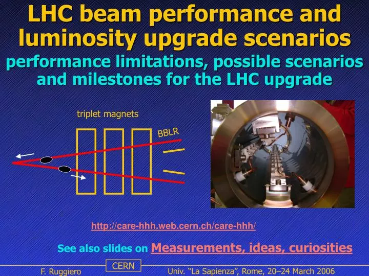
LHC beam performance and luminosity upgrade scenarios. triplet magnets. BBLR. performance limitations, possible scenarios and milestones for the LHC upgrade. http://care-hhh.web.cern.ch/care-hhh/. See also slides on Measurements, ideas, curiosities. Outline.

E N D
LHC beam performance and luminosity upgrade scenarios triplet magnets BBLR performance limitations, possible scenarios and milestones for the LHC upgrade http://care-hhh.web.cern.ch/care-hhh/ See also slides onMeasurements, ideas, curiosities
Outline • Time scale and potential of an LHC upgrade • LHC commissioning strategy and beam parameters • Machine performance limitations • Luminosity optimization and upgrade paths • Luminosity lifetime: peak vs integrated luminosity • LHC luminosity upgrade scenarios: • ultimate performance without hardware changes • upgrade of the Interaction Regions • new bunch-shortening RF system and cryogenic loads • collimation, beam-beam compensation and crab cavities • milestones and baseline design LHC beam performance and luminosity upgrade scenarios
Time scale of an LHC upgrade radiation damage limit ~700 fb-1 time to halve error integrated L L at end of year ultimate luminosity design luminosity courtesy J. Strait • the life expectancy of LHC IR quadrupole magnets is estimated to be <10 years owing to high radiation doses • the statistical error halving time will exceed 5 years by 2011-2012 • therefore, it is reasonable to plan a machine luminosity upgrade based on new low-ß IR magnets before ~2015 LHC beam performance and luminosity upgrade scenarios
luminosity versus energy upgrade Courtesy of Michelangelo Mangano F. Ruggiero & W.Scandale, LHC luminosity upgrade - report from LHC-LUMI-05
Chronology of LHC Upgrade studies • Summer 2001: two CERN task forces investigate physics potential (CERN-TH-2002-078) and accelerator aspects (LHC Project Report 626) of an LHC upgrade by a factor 10 in luminosity and 2-3 in energy • March 2002: LHC IR Upgrade collaboration meeting http://cern.ch/lhc-proj-IR-upgrade • October 2002: ICFA Seminar at CERN on “Future Perspectives in High Energy Physics” • 2003: US LHC Accelerator Research Program (LARP) • 2004: CARE-HHH European NetworkonHighEnergyHighIntensityHadronBeams • November 2004: first CARE-HHH-APD Workshop(HHH-04) on “Beam Dynamics in Future Hadron Colliders and Rapidly Cycling High-Intensity Synchrotrons”, CERN-2005-006 • September 2005: CARE-HHH Workshop(LHC-LUMI-05) on “Scenarios for the LHC Luminosity Upgrade” http://care-hhh.web.cern.ch/CARE-HHH/LUMI-05/ LHC beam performance and luminosity upgrade scenarios
Roadmap for the upgrade of the European accelerator infrastructure (LHC and GSI accelerator complex) luminosity and energy upgrade for the LHC pulsed SC high intensity synchrotrons for the GSI and LHC complex R&D and experimental studies at existing hadron accelerators select and develop technologies providing viable design options Coordinate activities and foster future collaborations Disseminate information The CARE-HHH Network Mandate Coordinate and integrate the activities of the accelerator and particle physics communities, in a worldwide context, towards achieving superior High-Energy High-Intensity Hadron-Beam facilities for Europe • HHH coordination: F. Ruggiero (CERN) & W. Scandale (CERN) • Advancement in Acc. Magnet Technology (AMT): L. Rossi (CERN) & L. Bottura (CERN) • Novel Meth. for Acc. Beam Instrumentation (ABI): H. Schmickler (CERN) & K. Wittenburg (DESY) • Accelerator Physics and Synchrotron Design (APD): F. Ruggiero (CERN) & F. Zimmermann (CERN) F. Ruggiero & W.Scandale, LHC luminosity upgrade - report from LHC-LUMI-05
Nominal LHC parameters LHC beam performance and luminosity upgrade scenarios
LHC upgrade paths/limitations • Peak luminosity at the beam-beam limit L~ I/b* • Total beam intensity I limited by electron cloud, collimation, injectors • Minimum crossing angle depends on beam intensity: limited by triplet aperture • Longer bunches allow higher bb-limit for Nb/en: limited by the injectors • Less ecloud and RF heating for longer bunches: ~50% luminosity gain for flat bunches longer than b* • Event pile-up in the physics detectors increases with Nb • Luminosity lifetime at the bb limit depends only on b* ⇒ reduce Tturnaround to increase integrated lumi longer bunches larger crossing angle I=1.72 A I=0.86 A ultimate bb limit more bunches I=0.58 A nominal LHC beam performance and luminosity upgrade scenarios
Expected factors for the LHC luminosity upgrade The peak LHC luminosity can be multiplied by: • factor 2.3 from nominal to ultimate beam intensity (0.58 0.86 A) • factor 2 (or more?) from new low-beta insertions with ß* = 0.25 m Tturnaround~10 h∫Ldt~ 3 x nominal ~ 200/(fb*year) Major hardware upgrades (LHC main ring and injectors) are needed to exceed ultimate beam intensity. The peak luminosity can be increased by: • factor 2 if we can double the number of bunches (maybe impossible due to electron cloud effects) or increase bunch intensity and bunch length Tturnaround~10 h∫Ldt~ 6 x nominal ~ 400/(fb*year) Increasing the LHC injection energy to 1 TeV would potentially yield: • factor ~2 in peak luminosity (2 x bunch intensity and 2 x emittance) • factor 1.4 in integrated luminosity from shorter Tturnaround~5 h thus ensuring L~1035 cm-2 s-1 and ∫Ldt~ 9 x nominal ~ 600/(fb*year) LHC beam performance and luminosity upgrade scenarios
Challenge of a Cold Machine LHC beam performance and luminosity upgrade scenarios
LHC Cleaning System (R. Assmann) Two-stage cleaning (phase 2) Two-stage cleaning (phase 1) 43 Single-stage cleaning No collimation Pilot LHC beam performance and luminosity upgrade scenarios
Collimation & Machine Protection LHC beam performance and luminosity upgrade scenarios
Constraints for LHC commissioning • Only 8/20 LHC dump dilution kickers available during the first two years of operationtotal beam intensity in each LHC ring limited to 1/2 of its nominal value • According to SPS experience and to electron cloud simulations, the initial LHC bunch intensity Nb can reach and possibly exceed its nominal value for 75 ns bunch spacing, while it may be limited to about 1/3 of its nominal value for 25 ns spacing • Machine protection and collimation favours initial operation with lower beam power and lower transverse beam density. Simple graphite collimators may limit maximum transverse energy density to about 1/2 of its nominal value • Emittance preservation from injection to physics conditions will require a learning curve do not assume transverse emittance smaller than nominal, even for reduced bunch intensity • Initial operation with relaxed parameters is strongly favoured higher ß*, reduced crossing angle, and fewer parasitic collisions LHC beam performance and luminosity upgrade scenarios
LHC beam commissioningMike Lamont, Chamonix 2005 workshop 43 on 43 with 3 to 4 x 10¹⁰ ppb to 7 TeV • No parasitic encounters • No crossing angle • No long range beam-beam • Larger aperture • Instrumentation • Good beam for RF, Vacuum… • Lower energy densities • Reduced demands on beam dump system • Collimation • Machine protection • Luminosity • 1030 cm-2s-1 at 18 m • 2 x 1031 cm-2s-1 at 1 m LHC beam performance and luminosity upgrade scenarios
LHC beam commissioningMike Lamont, Chamonix 2005 workshop LHC beam performance and luminosity upgrade scenarios
Steps to reach nominal LHC luminosity Possible scenarios with 75 ns and 25 ns bunch spacing for early LHC runs with integrated luminosity of about 10 fb-1 in 200 fills, assuming an average physics run time Trun = 14 h and Tturnaround=10 h. LHC beam performance and luminosity upgrade scenarios
Luminosity optimization transverse beam size at IP normalized emittance peak luminosity for head-on collisions round beams, short Gaussian bunches Collisions with full crossing angle qc reduce luminosity by a geometric factor F maximum luminosity below beam-beam limit ⇒ short bunches and minimum crossing angle (baseline scheme) H-V crossings in two IP’s ⇒ no linear tune shift due to long range total linear bb tune shift also reduced by F I = nbfrevNb total beam current • long range beam-beam • collective instabilities • synchrotron radiation • stored beam energy Nb/en beam brightness • head-on beam-beam • space-charge in the injectors • transfer dilution LHC beam performance and luminosity upgrade scenarios
If bunch intensity and brightness are not limited by the injectors or by other effects in the LHC (e.g. electron cloud) ⇒ luminosity can be increased without exceeding beam-beam limit DQbb~0.01 by increasing the crossing angle and/or the bunch length Express beam-beam limited brilliance Nb/εn in terms of maximum total beam-beam tune shift DQbb, then At high beam intensities or for large emittances, the performance will be limited by the angular triplet aperture LHC beam performance and luminosity upgrade scenarios
Minimum crossing angle Beam-Beam Long-Range collisions: • perturb motion at large betatron amplitudes, where particles come close to opposing beam • cause ‘diffusive’ (or dynamic) aperture, high background, poor beam lifetime • increasing problem for SPS, Tevatron, LHC, i.e., for operation with larger # of bunches dynamic aperture caused by npar parasitic collisions around two IP’s higher beam intensities or smaller b* require larger crossing angles to preserve dynamic aperture and shorter bunches to avoid geometric luminosity loss baseline scaling: qc~1/√b* , sz~b* angular beam divergence at IP LHC beam performance and luminosity upgrade scenarios
Schematic of a super-bunch collision, consisting of ‘head-on’ and ‘long-range’ components. The luminosity for long bunches having flat longitudinal distribution is ~1.4 times higher than for conventional Gaussian bunches with the same beam-beam tune shift and identical bunch population (see LHC Project Report 627) LHC beam performance and luminosity upgrade scenarios
Schematic of reduced electron cloud build up for a long bunch. Most electrons do not gain any energy when traversing the chamber in the quasi-static beam potential negligible heat load [after V. Danilov] LHC beam performance and luminosity upgrade scenarios
• beam-beam tune spread of 0.01 • L = 1034 cm-2s-1 in ATLAS and CMS • Halo collisions in ALICE • Low-luminosity in LHCb Nominal LHC performance Scenarios for the luminosity upgrade • ultimate performancewithouthardware changes(phase 0) • maximum performance withonly IRchanges (phase 1) • maximum performance with“major”hardware changes(phase 2) Phase 0:steps to reachultimate performancewithout hardware changes: • collide beams only in IP1 and IP5 with alternatingH-V crossing • increase Nb up to thebeam-beam limitL = 2.3 x 1034 cm-2 s-1 • increase the dipole field to9T (ultimate field)Emax = 7.54 TeV The ultimate dipole field of 9 T corresponds to a beam current limited by cryogenics and/or by beam dump/machine protection considerations. LHC beam performance and luminosity upgrade scenarios
Scenarios for the luminosity upgrade Phase 1:steps to reach maximum performance with onlyIR changes • Modify the insertion quadrupoles and/or layout ß* = 0.25 m • Increasecrossing angle cby √2 c = 445 µrad • IncreaseNbup to ultimate intensity L = 3.3 x 1034 cm-2s-1 • Halvezwith high harmonic RF system L = 4.6 x 1034 cm-2s-1 • Double theno. of bunchesnb(and increase c ) L = 9.2 x 1034 cm-2s-1 excluded by electron cloud? Step 5 belongs to Phase 2 Step 4) requires a new RF system providing • an accelerating voltage of 43 MV at 1.2 GHz • a power of about 11 MW/beam • longitudinal beam emittance reduced to 1.8 eVs • horizontalIntra-Beam Scattering (IBS)growth time decreases by ~ √2 Operational consequences of step 5) exceeding ultimate beam intensity • upgrade LHC cryogenics, collimation, RF and beam dump systems • the electronics of all LHC beam position monitors should be upgraded • possibly upgrade SPS RF system and other equipment in the injectors LHC beam performance and luminosity upgrade scenarios
luminosity upgrade: baseline scheme 1.0 0.58 A reduce sz by factor ~2 using higher frf & lower e|| (largerqc ?) qc>qmindue to LR-bb increase Nb restore F BBLR compen-sation bb limit? or decouple L and F crab cavities reduce qc (squeeze b*) no 0.86 A yes 2.3 reduce b* by factor ~2 new IR magnets use large qc & pass each beam through separate magnetic channel 4.6 0.86 A if e-cloud, dump & impedance ok increase nb by factor ~2 simplified IR design with large qc peak luminosity gain 9.2 1.72 A beam current
luminosity upgrade: Piwinski scheme decrease F reduce b* by factor ~2 new IR magnets 1.0 increase szqc 0.58 A superbunches? flatten profile? increase Nb reduce #bunches to limit total current? yes no 7.7 15.5 luminosity gain ? 0.86 A 1.72 A beam current
Various LHC upgrade options LHC beam performance and luminosity upgrade scenarios
Heat loads per beam aperture for various LHC upgrade options LHC beam performance and luminosity upgrade scenarios
Events per bunch crossing and beam lifetime due to nuclear p-p collisions sbb=60 mb total inelastic cross section beam intensity halving time due to nuclear p-p collisions at two IP’s with total cross section sTOT=110 mb nuclear scattering lifetime at the beam-beam limit depends only on b* ! luminosity lifetime: assumes radiation damping compensates diffusion exponential luminosity lifetime due to nuclear p-p interactions LHC beam performance and luminosity upgrade scenarios
Optimum run time and effective luminosity The optimum run time and the effective luminosity are universal functions of Tturnaround/tL When the beam lifetime is dominated by nuclear proton-proton collisions, then tL~tN/1.54 and the effective luminosity is a universal functions of Tturnaround/b* LHC beam performance and luminosity upgrade scenarios
Effective luminosity for various upgrade options LHC beam performance and luminosity upgrade scenarios
Interaction Region upgrade goal: reduce b* by at least a factor 2 options: NbTi ‘cheap’ upgrade, NbTi(Ta), Nb3Sn new quadrupoles new separation dipoles maximize magnet aperture, minimize distance to IR factors driving IR design: • minimize b* • minimize effect of LR collisions • large radiation power directed towards the IRs • accommodate crab cavities and/or beam-beam compensators. Local Q’ compensation scheme? • compatibility with upgrade path LHC beam performance and luminosity upgrade scenarios
IR ‘baseline’ schemes crab cavity triplet magnets triplet magnets BBLR short bunches & minimum crossing angle & BBLR crab cavities & large crossing angle LHC beam performance and luminosity upgrade scenarios
alternative IR schemes dipole magnets dipole triplet magnets triplet magnets dipole first & small crossing angle dipole first & large crossing angle & long bunches or crab cavities reduced # LR collisions collision debris hit D1 LHC beam performance and luminosity upgrade scenarios
Dipoles first and doublet focusing Features • Requires beams to be in separate focusing channels • Fewer magnets • Beams are not round at the IP • Polarity of Q1 determined by crossing plane – larger beam size in the crossing plane to increase overlap • Opposite polarity focusing at other IR to equalize beam-beam tune shifts • Significant changes to outer triplet magnets in matching section. Q1 D2 Q2 IP D1 D2 Focusing symmetric about IP Tanaji Sen, Doublet optics
Flat beams • Interesting approach, flat beams could increase luminosity by ~20-30% with reduced crossing angle • Symmetric doublets studied by J. Johnstone (FNAL) require separate magnetic channels, i.e. dipole-first, Crab cavities or special quads • Tune footprints are broader than for round beams, since there is only partial compensation of parasitic beam-beam encounters by the H/V crossing scheme. More work needed to evaluate nonlinear resonance excitation. • Probably requires BBLR compensation • Recently S. Fartoukh has found a more interesting flat beam solution with anti-symmetric LHC baseline triplets LHC upgrade scenarios
Beam aspect ratio vs triplet aperture (1/5) • Beam screen orientation for H/V scheme • In both cases, H-separation of about 9.5*max(sx,b1 ,sx,b2) Effect of decreasing the beam aspect ratio at the IP (and increasing the vert. X-angle) • In both cases, V-separation of about 9.5*max(sy,b1 ,sy,b2) Effect of increasing the beam aspect ratio at the IP (and decreasing the vert. X-angle) • Find the optimum matching between beam-screen and beam aspect ratio S. Fartoukh, ABP-RLC meeting, 28-10-2005
Pushing the luminosity by 10-20% • All these cases being allowed by the nominal LHC hardware:layout, power supply, optics antisymmetry, b.s. orientation in the triplets (only changing the present H/V scheme into V/H scheme)! S. Fartoukh, ABP-RLC meeting, 28-10-2005
‘cheap’ IR upgrade in case we need to double LHC luminosity earlier than foreseen triplet magnets BBLR short bunches & minimum crossing angle & BBLR each quadrupole individually optimized (length & aperture) reduced IP-quad distance from 23 to 22 m conventional NbTi technology: b*=0.25 m is possible LHC beam performance and luminosity upgrade scenarios
Several LHC IR upgrade options are being explored : • quadrupole-first and dipole-first solutions based on conventional NbTi technology and on high-field Ni3Sn magnets, possibly with structured SC cable • energy deposition, absorbers, and quench limits • schemes with Crab cavities as an alternative to the baseline bunch shortening RF system at 1.2 GHz to avoid luminosity loss with large crossing angles • early beam separation by a “D0” dipole located a few metres away from the IP (or by tilted experimental solenoids?) may allow operation with a reduced crossing angle. Open issues: compatibility with detector layout, reduced separation at first parasitic encounters, energy deposition by the collision debris • local chromaticity correction schemes • flat beams, i.e. a final doublet instead of a triplet. Open issues: compensation of long range beam-beam effects with alternating crossing planes LHC beam performance and luminosity upgrade scenarios
Crab cavities vs bunch shortening Crab cavities combine advantages of head-on collisions and large crossing angles require lower voltages compared to bunch shortening RF systems but tight tolerance on phase jitter to avoid emittance growth Comparison of timing tolerances LHC beam performance and luminosity upgrade scenarios
Crab Cavities LHC beam performance and luminosity upgrade scenarios
Motivation of Beam-Beam compensation studies • Provide more LHC luminosity earlier Space is reserved in the LHC for the wires. An early test in RHIC will determine the effectiveness of the compensation and possibly address the challenges to the compensation. If effective, will allow a smaller crossing angle and more beam intensity. • Provide direction to an IR upgrade path If compensation is proven to be effective, then the quadrupole-first option, possibly with flat beams, seems to be a more natural path for the IR upgrade. Otherwise, the dipole-first option will be more attractive. LHC beam performance and luminosity upgrade scenarios
Lessons from the SPS experiments No wires activated • Compensating 1 wire with another wire at nearly the same phase “works” • Compensation is tune dependent • Current sensitivity • Alignment sensitivity • Equivalent crossings in the same plane led to better lifetimes than alternating planes • Beam lifetime t ~ d3 d is the beam-wire distance Higher power law expected given the proximity of high order resonances Nearly perfect compensation Both wires on 1 wire on LHC beam performance and luminosity upgrade scenarios
2nd prototype BBLR in the CERN SPS has demonstrated benefit of compensation G. Burtin, J. Camas, J.-P. Koutchouk, F. Zimmermann et al. LHC beam performance and luminosity upgrade scenarios
Lessons from RHIC experiment • Study at injection energy with 1 bunch and 1 parasitic interaction per beam • There is an effect to compensate, even with 1parasitic • Drop in lifetime seen for beam separations < 7 σ • Effect is very tune dependent • How important are machine nonlinearities and other time dependent effects? • Did they change with the beam-beam separation? LHC beam performance and luminosity upgrade scenarios
Wire compensation at RHIC • Compensation of 1 wire by another wire worked well in the SPS under LHC conditions. • Real test of the compensation principle requires 2 beams • Beam studies in RHIC show that parasitic interactions have strong influence on beam loss • Favorable location for wire has been found in IR6, phase advance to parasitic ~6 degrees at top energy Proposed wire location Location of parasitic LHC beam performance and luminosity upgrade scenarios
Milestones for future LHC Upgrade machine studies • 2006: installation and test of a beam-beam long range compensation system at RHIC to be validated with colliding beams • 2006/2007: new SPS experiment for crystal collimation, complementary to Tevatron results • 2006: installation and test of Crab cavities at KEKB to validate higher beam-beam limit and luminosity with large crossing angles • 2007: if KEKB test successful, test of Crab cavities in a hadron machine (RHIC?) to validate low RF noise and emittance preservation • 2007-2009: LHC running-in and first machine studies on collimation and beam-beam LHC beam performance and luminosity upgrade scenarios
Tentative conclusions for the LHC IR Upgrade • We do need a back-up or intermediate IR upgrade option based on NbTi magnet technology. What is the maximum luminosity? • A vigorous R&D programme on Nb3Sn magnets should start at CERN asap, in parallel to the US-LARP programme, to be ready for 1035 luminosity in ~2015 • Alternative IR layouts (quadrupole-first, dipole-first, D0, flat beams, Crab cavities) will be rated in terms of technological and operational risks/advantages LHC beam performance and luminosity upgrade scenarios
Towards a baseline design Following the approach proposed by Barry Barish for the ILC, we propose to: • Define aBaseline, i.e. a forward looking configuration which we are reasonably confident can achieve the required LHC luminosity performance and can be used to give an accurate cost estimate by mid-end 2006 in a “Reference Design Report” • Identify Alternative Configurations and rate them in terms of technological and operational risks/advantages • Identify R&D (at CERN and elsewhere) • To support the baseline • To develop the alternatives LHC beam performance and luminosity upgrade scenarios