Download
1 / 15
150 likes | 151 Views
This article discusses the target system of a neutrino factory, including the production target and magnetized pion-decay channel. It provides preliminary cost estimates and outlines the desirable proton beam assumptions and target baseline.

E N D
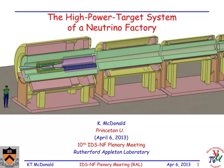
The High-Power-Target Systemof a Neutrino Factory K. McDonald Princeton U. (April 6, 2013) 10th IDS-NF Plenary Meeting Rutherford Appleton Laboratory
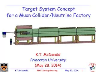
The Target System of a Muon-Collider or Neutrino Factory In the IDS-NF costing scenario, the Target System includes the production target and the magnetized pion-decay channel. This system is about 50 m long. Very preliminary cost estimate now exists. (A Fermicentric vision)
Target and Capture Topology: Solenoid Desire 1014/s from 1015p/s ( 4 MW proton beam) Superconducting magnets • R.B. Palmer (BNL, 1994) proposed a 20-T solenoidal capture system. • Low-energy 's collected from side of long, thin cylindrical target. • Solenoid coils can be some distance from proton beam. • 10-year life against radiation damage at 4 MW. Liquid mercury jet target replaced every pulse. • Proton beam readily tilted with respect to magnetic axis. • Beam dump (mercury pool) out of the way of secondary 's and 's. Present Target Concept Tungsten beads, He gas cooled Be window Proton beam and Mercury jet Mercury collection pool With splash mitigator Resistive magnets Shielding of the superconducting magnets from radiation is a major issue. Magnet stored energy ~ 3 GJ! 5-T copper magnet insert; 15-T Nb3Sn coil + 5-T NbTi outsert. Desirable to replace the copper magnet by a 20-T HTC insert.
Target Baseline: Proton Beam Assumptions • Proton Beam Energy 8 GeV • Rep Rate 50 Hz • Bunch Structure 3 bunches, 240 sec total • Bunch Width 2 1 ns • Beam Radius 1.2 mm (rms) • Beam β* ≥ 30 cm • ≤ 5 () m • Beam Power 4 MW (3.125 1015 protons/sec) http://www.hep.princeton.edu/~mcdonald/mumu/target/hkirk/hkirk_101811.pdf IDS Plenary Meeting, Oct. 18, 2011
Target System Baseline • Target type Free mercury jet • Jet diameter 8 mm • Jet velocity 20 m/s • Jet/Solenoid Axis Angle 96 mrad • Proton Beam/Solenoid Axis Angle 96 mrad • Proton Beam/Jet Angle 27 mrad • Capture Solenoid Field Strength 20 T
Jet/Solenoid/Proton-Beam Geometry All “useful” pions for the Neutrino Factory produced at z < 0, Center of beam-jet interaction is at z = - 37.5 cm.
Optimization of Pion Production via MARS1512 Optimization of beam energy, radius, angle, as well as jet radius and angle, for both Hg and Ga. X. Ding et al., MOPPC044, IPAC12 http://www.hep.princeton.edu/~mcdonald/mumu/target/ipac12/MOPPC044.pdf
Proton Beam Emittance and * Beam radius is fixed at 0.12 cm at z = -37.5 cm. For geometrical rms emittance 5 π μm, need β* = βx = βy = 0.3 m. But, prefer β* = βx = βy = 0.65 m. (X. Ding) http://www.hep.princeton.edu/~mcdonald/mumu/target/Ding/ding_100412.pdf
Proton Beam Final Focus with β*of 0.65 m Final focus consists of 4 room-temperature quads. Beam Window Position Target Position To do: Move last quad to z - 4 m, and determine largest for which r = 1.2 mm at target. Smaller * J. Pasternak, Aug 7, 2012 http://www.hep.princeton.edu/~mcdonald/mumu/target/Pasternak/pasternak_080712.pdf
Mercury Target Module with Beam Dump/Collection Pool Baseline: Mercury target module (double containment vessel) is surrounded by the 5-T copper magnet (all within the 15-T SC magnet. [Difficult to build.] (V. Graves) Alternative concept has no 5-T copper magnet (only 15-T magnet. Both concept incorporate a Mercury-collection pool as beam dump. Splash mitigation a remaining challenge.
20-T Field on Target “Tapers” in 15 m to 1.5 T in Decay Channel Module could be repeated until buncher at z ~ 60 m z = 0 1.5 T 20 T z = 15 m “IDS120k” configuration The taper exchanges longitudinal and transverse phase space. May be advantageous to use shorter taper, and higher field in decay channel.
Radiation Damage to Nb Superconductor The ITER project quotes the lifetime radiation dose to the superconducting magnets as 1022n/m2 for reactor neutrons with E > 0.1 MeV. This is also 107 Gray = 104 J/g accumulated energy deposition. For a lifetime of 10 “years” of 107 s each, the peak rate of energy deposition would be 104 J/g / 108 s = 10-4 W/g = 0.1 mW/g (= 1 MGray/year of 107 s). The ITER Design Requirements document, http://puhep1.princeton.edu/~mcdonald/examples/magnets/iter_fdr_DRG1.pdf reports this as 1 mW/cm3 of peak energy deposition (which seems to imply magnet 10 g/cm3). Damage to Nb-based superconductors appears to become significant at doses of 2-3 1022n/m2: A. Nishimura et al., Fusion Eng. & Design 84, 1425 (2009) http://puhep1.princeton.edu/~mcdonald/examples/magnets/nishimura_fed_84_1425_09.pdf Reviews of these considerations for ITER: J.H. Schultz, IEEE Symp. Fusion Eng. 423 (2003) http://puhep1.princeton.edu/~mcdonald/examples/magnets/schultz_ieeesfe_423_03.pdf http://puhep1.princeton.edu/~mcdonald/examples/magnets/schultz_cern_032205.pdf Reduction of critical current of various Nb-based Conductors as a function of reactor neutron fluence. From Nishimura et al.
High Levels of Energy Deposition in the Target System Power deposition in the superconducting magnets and the He-gas-cooled tungsten shield inside them, according to a FLUKA simulation. Approximately2.4 MW must be dissipated in the shield. Some 800 kW flows out of the target system into the downstream beam-transport elements. Total energy deposition in the target magnet string is ~ 1 kW @ 4k. Peak energy deposition is about 0.03 mW/g. (J. Back, N. Souchlas)
Shielding of the Superconducting Solenoids Drives the Design • MARS15 simulations (with MCNP data for very low particle energies) indicate that use of He-gas-cooled, tungsten-bead shielding • Inner radius of the 15-T solenoid around the target must be 120 cm; • Stored energy in target magnet system ~ 3 GJ (same as LHC octant). • Target-magnet module weighs ~ 200 tons Need big crane for assembly. • Of the 4-MW proton beam power, some 500 kW continues down the 30-cm-radius beam pipe beyond z = 15 m (= end of taper); mostly in the form of GeV scattered protons. • This energy would eventually be deposited in the rf cavities and low-Z absorbers of the cooling section, if not removed earlier. • A chicane + proton absorber in the decay channel (15 < z < 60 m) will mitigate this issue. • May be favorable to use HTS for • the decay region/chicane magnets. • (C. Rogers, P. Snopok, D. Neuffer, • R. Weggel)
RDR Readiness • Blue = “ready”, Red = “not so ready” • Target System Overview (-3 < z < 65 m, including “chicane”) • Alternatives: Ga or C targets; shorter taper; 15-T peak field; 2-2.5/T min field • Particle Production Simulations • Beam-Jet Interaction (data from MERIT expt. + simulations) • Energy Deposition simulations for 0 < z < 15 m • Energy Deposition simulations for 15 < z < 65 m • Magnet configuration for 0 < z < 15 m • Magnet configuration for 15 < z < 65 m • Mercury handling system • Magnet power supplies • Cooling systems • Civil engineering • Utilities • Safety