Download
1 / 1
10 likes | 115 Views
Progress on Design Studies of a High-Luminosity Ring-Ring Electron-Ion Collider at CEBAF and Its Low to Medium Energy Staging Approach*

E N D
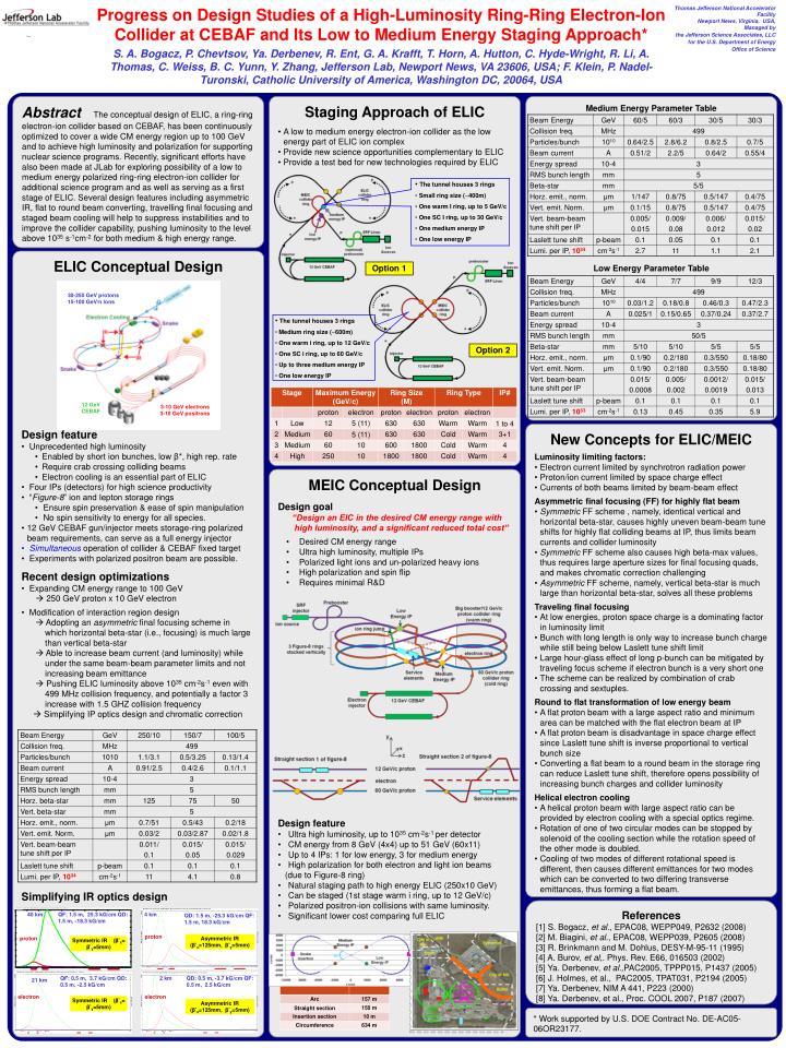
Progress on Design Studies of a High-Luminosity Ring-Ring Electron-Ion Collider at CEBAF and Its Low to Medium Energy Staging Approach* S. A. Bogacz, P. Chevtsov, Ya. Derbenev, R. Ent, G. A. Krafft, T. Horn, A. Hutton, C. Hyde-Wright, R. Li, A. Thomas, C. Weiss, B. C. Yunn, Y. Zhang, Jefferson Lab, Newport News, VA 23606, USA; F. Klein, P. Nadel-Turonski, Catholic University of America, Washington DC, 20064, USA Thomas Jefferson National Accelerator Facility Newport News, Virginia, USA, Managed by the Jefferson Science Associates, LLC for the U.S. Department of Energy Office of Science • The tunnel houses 3 rings • Small ring size (~400m) • One warm I ring, up to 5 GeV/c • One SC I ring, up to 30 GeV/c • One medium energy IP • One low energy IP • The tunnel houses 3 rings • Medium ring size (~600m) • One warm i ring, up to 12 GeV/c • One SC i ring, up to 60 GeV/c • Up to three medium energy IP • One low energy IP 30-250 GeV protons 15-100 GeV/n ions 12 GeV CEBAF 3-10 GeV electrons 3-10 GeV positrons 40 km QF: 1.5 m, 25.3 kG/cm QD: 1.5 m, -18.3 kG/cm 4 km QD: 1.5 m, -25.3 kG/cm QF: 1.5 m, 18.3 kG/cm proton proton Asymmetric IR (β*x=125mm, β*y=5mm) Symmetric IR (β*x= β*y=5mm) QF: 0.5 m, 3.7 kG/cm QD: 0.5 m, -2.5 kG/cm 2 km QD: 0.5 m, -3.7 kG/cm QF: 0.5 m, 2.5 kG/cm 21 km electron electron Symmetric IR (β*x= β*y=5mm) Asymmetric IR (β*x=125mm, β*y=5mm) AbstractThe conceptual design of ELIC, a ring-ring electron-ion collider based on CEBAF, has been continuously optimized to cover a wide CM energy region up to 100 GeV and to achieve high luminosity and polarization for supporting nuclear science programs. Recently, significant efforts have also been made at JLab for exploring possibility of a low to medium energy polarized ring-ring electron-ion collider for additional science program and as well as serving as a first stage of ELIC. Several design features including asymmetric IR, flat to round beam converting, travelling final focusing and staged beam cooling will help to suppress instabilities and to improve the collider capability, pushing luminosity to the level above 1035 s-1cm-2 for both medium & high energy range. • Staging Approach of ELIC • A low to medium energy electron-ion collider as the low energy part of ELIC ion complex • Provide new science opportunities complementary to ELIC • Provide a test bed for new technologies required by ELIC • Medium Energy Parameter Table • Low Energy Parameter Table • ELIC Conceptual Design • Design feature • Unprecedented high luminosity • Enabled by short ion bunches, low β*, high rep. rate • Require crab crossing colliding beams • Electron cooling is an essential part of ELIC • Four IPs (detectors) for high science productivity • “Figure-8” ion and lepton storage rings • Ensure spin preservation & ease of spin manipulation • No spin sensitivity to energy for all species. • 12 GeV CEBAF gun/injector meets storage-ring polarized beam requirements, can serve as a full energy injector • Simultaneous operation of collider & CEBAF fixed target • Experiments with polarized positron beam are possible. • Recent design optimizations • Expanding CM energy range to 100 GeV • 250 GeV proton x 10 GeV electron • Modification of interaction region design • Adopting an asymmetric final focusing scheme in • which horizontal beta-star (i.e., focusing) is much large • than vertical beta-star • Able to increase beam current (and luminosity) while • under the same beam-beam parameter limits and not • increasing beam emittance • Pushing ELIC luminosity above 1035 cm-2s-1 even with • 499 MHz collision frequency, and potentially a factor 3 • increase with 1.5 GHZ collision frequency • Simplifying IP optics design and chromatic correction • Simplifying IR optics design Option 1 Option 2 • New Concepts for ELIC/MEIC • Luminosity limiting factors: • Electron current limited by synchrotron radiation power • Proton/ion current limited by space charge effect • Currents of both beams limited by beam-beam effect • Asymmetric final focusing (FF) for highly flat beam • Symmetric FF scheme , namely, identical vertical and horizontal beta-star, causes highly uneven beam-beam tune shifts for highly flat colliding beams at IP, thus limits beam currents and collider luminosity • Symmetric FF scheme also causes high beta-max values, thus requires large aperture sizes for final focusing quads, and makes chromatic correction challenging • Asymmetric FF scheme, namely, vertical beta-star is much large than horizontal beta-star, solves all these problems • Traveling final focusing • At low energies, proton space charge is a dominating factor in luminosity limit • Bunch with long length is only way to increase bunch charge while still being below Laslett tune shift limit • Large hour-glass effect of long p-bunch can be mitigated by traveling focus scheme if electron bunch is a very short one • The scheme can be realized by combination of crab crossing and sextuples. • Round to flat transformation of low energy beam • A flat proton beam with a large aspect ratio and minimum area can be matched with the flat electron beam at IP • A flat proton beam is disadvantage in space charge effect since Laslett tune shift is inverse proportional to vertical bunch size • Converting a flat beam to a round beam in the storage ring can reduce Laslett tune shift, therefore opens possibility of increasing bunch charges and collider luminosity • Helical electron cooling • A helical proton beam with large aspect ratio can be provided by electron cooling with a special optics regime. • Rotation of one of two circular modes can be stopped by solenoid of the cooling section while the rotation speed of the other mode is doubled. • Cooling of two modes of different rotational speed is different, then causes different emittances for two modes which can be converted to two differing transverse emittances, thus forming a flat beam. • MEIC Conceptual Design • Design goal • “Design an EIC in the desired CM energy range with • high luminosity, and a significant reduced total cost” • Desired CM energy range • Ultra high luminosity, multiple IPs • Polarized light ions and un-polarized heavy ions • High polarization and spin flip • Requires minimal R&D • Design feature • Ultra high luminosity, up to 1035 cm-2s-1 per detector • CM energy from 8 GeV (4x4) up to 51 GeV (60x11) • Up to 4 IPs: 1 for low energy, 3 for medium energy • High polarization for both electron and light ion beams • (due to Figure-8 ring) • Natural staging path to high energy ELIC (250x10 GeV) • Can be staged (1st stage warm i ring, up to 12 GeV/c) • Polarized positron-ion collisions with same luminosity. • Significant lower cost comparing full ELIC References [1] S. Bogacz, et al., EPAC08, WEPP049, P2632 (2008) [2] M. Biagini, et al., EPAC08, WEPP039, P2605 (2008) [3] R. Brinkmann and M. Dohlus, DESY-M-95-11 (1995) [4] A. Burov, et al,. Phys. Rev. E66, 016503 (2002) [5] Ya. Derbenev, et al.,PAC2005, TPPP015, P1437 (2005) [6] J. Holmes, et al., PAC2005, TPAT031, P2194 (2005) [7] Ya. Derbenev, NIM A 441, P223 (2000) [8] Ya. Derbenev, et al., Proc. COOL 2007, P187 (2007) * Work supported by U.S. DOE Contract No. DE-AC05-06OR23177.