Download
1 / 42
420 likes | 610 Views
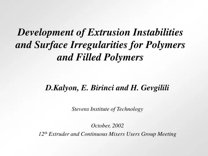
Development of Extrusion Instabilities and Surface Irregularities for Polymers and Filled Polymers. D.Kalyon, E. Birinci and H. Gevgilili Stevens Institute of Technology October, 2002 12 th Extruder and Continuous Mixers Users Group Meeting. Outline.

E N D
Development of Extrusion Instabilities and Surface Irregularities for Polymers and Filled Polymers D.Kalyon, E. Birinci and H. Gevgilili Stevens Institute of Technology October, 2002 12th Extruder and Continuous Mixers Users Group Meeting
Outline • We studied PDMS, HDPE and BAMO/AMMO-ETPE for wall slip behavior in steady torsional flow and development of surface irregularities in capillary flow • Compare with filled PDMS (10,20,40% by volume hollow glass spheres) and KCl Filled BAMO/AMMO.
Important points • Materials which do exhibit strong slip exhibit flow instabilities during extrusion commencing at the shear stress at which strong slip is observed. Incorporation of rigid particles at the right concentration eliminates all types of surface irregularities during extrusion. • Melt which does not exhibit strong slip for relatively high strains and shear rates does not exhibit surface irregularities in the same shear rate range. However, the incorporation of rigid particles introduces surface irregularities during extrusion.
Conclusion • It appears that the stability of stick or slip at the wall during extrusion governs the occurrence of surface irregularities. • It is not clear what controls the stability of the boundary condition.
HDA 601 high density polyethylene available from Exxon-Mobil Chemical Company Melt flow index=0.55 (according to ASTM D-1238) Density=0.933 g/cm3 (according to ASTM D-1505) • Polydimethylsiloxane (PDMS SE-30) manufactured by GE Silicones Density=0.98 g/cm3 at 30°C • A Thermoplastic Elastomer: BAMO-AMMO available from ATK Thiokol Propulsion
Structure of BAMO-AMMO Consisting of of 3, 3-bis (azidomethyl) oxetane, BAMO, which is a crystalline homopolymer and the soft block consisting of 3-azidometyl-3-metyloxetane, AMMO, which is an amorphous homopolymer, forming the soft block of this energetic thermoplastic elastomer
gׂ=70 s-1, t=0.1 s, g=7 Sample ejection from the gap gׂ=60 s-1 gׂ=50 s-1 gׂ=70 s-1 gׂ=23 s-1 gׂ=10 s-1 gׂ=5 s-1 gׂ=10 s-1, t=1 s, g=10 t=0 s, g=0 HDPE steady torsional flow
gׂ=70 s-1 gׂ=60 s-1 gׂ=25 s-1 gׂ=10 s-1 gׂ=50 s-1 gׂ=1 s-1 gׂ=0.1 s-1 HDPE steady torsional flow
gׂ=30 s-1 gׂ=40 s-1 gׂ=20 s-1 gׂ=5 s-1 gׂ=10 s-1 gׂ=2 s-1 gׂ=1 s-1 gׂ=0.1 s-1 gׂ=2 s-1, t=3.5 s, g=7 gׂ=40 s-1, t=0.15s, g=6 t=0 s, g=0 PDMS steady torsional flow
gׂ=30 s-1 gׂ=10 s-1 gׂ=5 s-1 gׂ=20 s-1 gׂ=2 s-1 gׂ=40 s-1 gׂ=1 s-1 gׂ=0.1 s-1 PDMS steady torsional flow, first normal stress difference
gׂ=200 s-1 gׂ=150 s-1 gׂ=100 s-1 gׂ=30 s-1 gׂ=10 s-1 gׂ=1 s-1 gׂ=0.1 s-1 BAMO/AMMO TPE steady torsional flow
Transducer overload gׂ=200 s-1 gׂ=150 s-1 gׂ=10 s-1 gׂ=100 s-1 gׂ=30 s-1 gׂ=1 s-1 gׂ=0.1 s-1 gׂ=0.05 s-1 BAMO/AMMO TPE steady torsional flow
Critical wall shear stress values at which strong wall slip is initiated in steady torsional flow • HDPE: • @ 170C tc=0.22 MPa • @ 190C tc= 0.22 MPa • @ 210C tc= 0.23 MPa • PDMS: • @ 10C tc= 0.067 MPa • @ 30C tc= 0.069 MPa • @ 50C tc= 0.068 MPa • No strong wall slip for BAMO/AMMO TPE for strains up to 20 even at shear rates as high as 200 s-1.
D=0.375” 45°angle D L The angle of convergence was varied between 15, 45 and 75 degrees.
Conclusions • The shear stress at the onset of catastrophic failure of the no-slip condition in steady torsional flow coincides with onset of flow instabilities in capillary flow • TPE which does not exhibit strong slip up to high strains (20) and strain rates (200 s-1) in steady torsional flow also does not exhibit flow instabilities in capillary flow
Conclusions • The critical shear stress at the point of catastrophic failure of the no-slip condition is temperature independent for PDMS and HDPE. • Results emphasize the central role played by wall slip in the development of the flow instabilities
What happens to development of surface irregularities in extrusion flow when we fill these polymers with rigid fillers?
1,000,000 100,000 CORRECTED SHEAR STRESS, Pa 10,000 0.01 0.10 1.00 10.00 -1 CORRECTED SHEAR RATE, s KCl filled BAMO/AMMO TPE
PDMS + Glass Sphere(10% by vol.) Mixture Corrected Shear Stress vs. Apparent Shear Rate Behavior Comparison of Different Diameters
D=0.098 g = 10 s-1 PDMS + Hallow Sphere Glass Particles ( 10% by vol.) Mixture
D=0.098 g = 20 s-1 PDMS + Hallow Sphere Glass Particles ( 10% by vol.) Mixture
D=0.098 g = 40s-1 PDMS + Hallow Sphere Glass Particles ( 10% by vol.) Mixture
D=0.0591 g = 45 s-1 PDMS + Hallow Sphere Glass Particles ( 10% by vol.) Mixture
D=0.0591 g = 45 s-1 D=0.098 g = 40s-1 D=0.0591 g = 91 s-1 D=0.0328 g = 53 s-1 PDMS + Hallow Sphere Glass Particles ( 10% by vol.) Mixture
D=0.0591 g = 45 s-1 D=0.098 g = 40s-1 D=0.098 g =98 s-1 PDMS + Hallow Sphere Glass Particles ( 10% by vol.) Mixture
D=0.0591 g = 45 s-1 D=0.098 g = 40s-1 D=0.0591 g = 182 s-1 D=0.0328 g = 53 s-1 PDMS + Hallow Sphere Glass Particles ( 10% by vol.) Mixture
D=0.0591 g = 45 s-1 D=0.098 g = 40s-1 D=0.0591 g = 454 s-1 D=0.0328 g = 53 s-1 PDMS + Hallow Sphere Glass Particles ( 10% by vol.) Mixture
g= 40 s-1 g= 10 s-1 PDMS + Glass Sphere(10% by vol.) Mixture Step Rate Experiment
PDMS + Glass Sphere(10% by vol.) Mixture Apparent Shear Stress vs. Apparent Shear Rate Behavior Comparison of Different Angle
a = 15° g = 18s-1 a = 45° g = 18s-1 a = 75° g = 18s-1 PDMS + Glass Sphere(10% by vol.) Mixture Apparent Shear Stress vs. Apparent Shear Rate Behavior Comparison of Different Angle
a = 45° g = 45s-1 a = 15° g = 45s-1 a = 75° g = 45s-1 PDMS + Glass Sphere(10% by vol.) Mixture Apparent Shear Stress vs. Apparent Shear Rate Behavior Comparison of Different Angle
a = 75° g = 90s-1 a = 45° g = 90s-1 a = 15° g = 90s-1 PDMS + Glass Sphere(10% by vol.) Mixture Apparent Shear Stress vs. Apparent Shear Rate Behavior Comparison of Different Angle
a = 75° g = 181s-1 a = 15° g = 181s-1 a = 45° g = 181s-1 PDMS + Glass Sphere(10% by vol.) Mixture Apparent Shear Stress vs. Apparent Shear Rate Behavior Comparison of Different Angle
a = 15° g = 454s-1 a = 45° g = 454s-1 a = 75° g = 454s-1 PDMS + Glass Sphere(10% by vol.) Mixture Apparent Shear Stress vs. Apparent Shear Rate Behavior Comparison of Different Angle
PDMS + Glass Sphere(20% by vol.) Mixture Corrected Shear Stress vs. Apparent Shear Rate Behavior Comparison of Different Diameters
g= 40 s-1 PDMS + Glass Sphere(40% by vol.) Mixture
PDMS + Glass Sphere Mixture Corrected Shear Stress vs. Apparent Shear Rate Behavior Comparison of Different Loaded Material
PDMS + Glass Sphere Mixture Apparent Shear Stress vs. Apparent Shear Rate Behavior Comparison of Different Loaded Material
PDMS + Glass Sphere Mixture Apparent Shear Stress vs. Apparent Shear Rate Behavior Comparison of Different Loaded Material
Conclusion • It appears that the stability of stick or slip at the wall during extrusion governs the occurrence of surface irregularities. • It is not clear what controls the stability of the boundary condition.
Acknowledgement • We acknowledge with gratitude the support of TACOM/ARDEC, NSWC/IH, BMDO/IST (ONR), DARPA, PBMA and various companies including Unilever, Duracell, Henkel-Loctite, GPU, and MPR which made this investigation possible.