Download
1 / 14
140 likes | 380 Views
Automation and Control of a limited size parking lot using PIC18 Microcontroller. Alaa Sharif Ali Ghamlouch Zaher Khattab. Presented to: Dr. Youmin Zhang. April 2011. Contents. Introduction The Hardware Circuit Diagram Flow Chart Sensing and Interrupts Actuation Feedback and Display

E N D
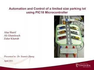
Automation and Control of a limited size parking lot using PIC18 Microcontroller Alaa Sharif Ali Ghamlouch Zaher Khattab Presented to: Dr. Youmin Zhang April 2011
Contents • Introduction • The Hardware • Circuit Diagram • Flow Chart • Sensing and Interrupts • Actuation • Feedback and Display • Conclusion • Future Work
Introduction • The objective of the project is to count number of cars entering and exiting the parking lot • Number of available lots is displayed on an LCD • Automation components used: Sensors, Servo Motors, LCD display, indicator LEDs • components are connected to microcontroller (PIC18F4431) to simulate the sensing, actuating, and feedback
The Hardware • PIC18F4431 Microcontrollers • 2 Sensors, each sensor consist of a IR transmitter & 40 KHz receiver • 555 timer • 2 Electric Servo motors (HiTEC HS-422) • LCD Display (2 Lines, Max 16 character in each line) • 4 indicating LEDs (2 Green, 2 Red)
Sensing • Introducing IR emitter-receiver sensor • Implementation of the IR emitter-receiver sensor using 555 timer
Sensing • Frequency Calibration IR emitter-receiver: • 0.693 (+) • == 2.5 * sec • is a variable resistor
Actuation • 2 servo motors controlling the opening and closing of gates • Generating delays to turn the motor(loop repetition)
Actuation • On and off delay defines duty cycle, period and frequency • Neutral: 1.5 ms high , 18.5 ms low • Rotation : 1.9 ms high, 18.1 ms low • Maintaining the position of the motor
Feedback and Display • Interrupt through sensors • Incrementing / decrementing a register to count available lots • Displaying available lots on LCD • Indicator LEDs to indicate opening and closing of gates
Conclusion • Combination between hardware and software was achieved with success • Fulfilling the interface between the IR emitter receiver sensor, the 2 servo motors, the LCD and the four indicator LEDs
Future Work • Use of vision system to indicate presence of cars on gate • Fully automated vision system indicating number of available slots and controlling the gates • Use of IR sensors on all parking slots to indicate a vacant one, and displaying slot’s number on LCD