Download
1 / 54
540 likes | 647 Views
Input and Output. CS502 Operating Systems Fall 2006 (Slides include materials from Operating System Concepts , 7 th ed., by Silbershatz, Galvin, & Gagne and from Modern Operating Systems , 2 nd ed., by Tanenbaum). Overview. What is I/O? Principles of I/O hardware

E N D
Input and Output CS502 Operating SystemsFall 2006 (Slides include materials from Operating System Concepts, 7th ed., by Silbershatz, Galvin, & Gagne and from Modern Operating Systems, 2nd ed., by Tanenbaum) Input & Output
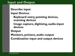
Overview • What is I/O? • Principles of I/O hardware • Principles of I/O software • Methods of implementing input-output activities • Organization of device drivers • Specific kinds of devices (Silbershatz, Chapter 13) Input & Output
I/O • The largest, most complex subsystem in OS • Most lines of code • Highest rate of code changes • Where OS engineers most likely to work • Difficult to test thoroughly • Make-or-break issue for any system • Big impact on performance and perception • Bigger impact on acceptability in market Input & Output
Memory Device Device Hardware Organization (simple) memory bus CPU Input & Output
Ether-net SCSI USB Modem Soundcard Printer Mouse Key-board Hardware Organization (typical Pentium) Main Memory AGP Port Level 2 cache CPU Bridge Graphics card Moni-tor ISA bridge PCI bus IDE disk ISA bus Input & Output
Kinds of I/O Devices • Character (and sub-character) devices • Mouse, character terminal, joy stick, some keyboards • Block transfer • Disk, tape, CD, DVD • Network • Clocks • Internal, external • Graphics • GUI, games • Multimedia • Audio, video • Other • Sensors, controllers Input & Output
Controlling an I/O Device • A function of host CPU architecture • Special I/O instructions • Opcode to stop, start, query, etc. • Separate I/O address space • Kernel mode only • Memory-mapped I/O control registers • Each register has a physical memory address • Writing to data register is output • Reading from data register is input • Writing to control register causes action • Can be mapped to user-level virtual memory Input & Output
Character Device (example) • Data register: • Register or address where data is read from or written to • Very limited capacity (at most a few bytes) • Action register: • When writing to register, causes a physical action • Reading from register yields zero • Status register: • Reading from register provides information • Writing to register is no-op Input & Output
Block Transfer Device (example) • Buffer address register: • Points to area in physical memory to read or write data or • Addressable buffer for data • E.g., network cards • Action register: • When writing to register, initiates a physical action or data transfer • Reading from register yields zero • Status register: • Reading from register provides information • Writing to register is no-op Input & Output
DMA(Direct Memory Access) • Ability to control block devices to autonomously read from and/or write to main memory • (Usually) physical addresses • (Sometimes) performance degradation of CPU • Transfer address • Points to location in physical memory • Action register: • Initiates a reading of control block chain to start actions • Status register: • Reading from register provides information Input & Output
Direct Memory Access (DMA) Operation of a DMA transfer Input & Output
Programmed DMA physicalmemory DMA controllerFirst control block disk controls … operationaddress Count control infonext operationaddress Count control infonext operationaddress Count control infonext Input & Output
Programmed DMA (continued) • DMA control register points to first control block in chain • Each DMA control block has • Action & control info for a single transfer of one or more blocks • Data addresses in physical memory • (optional) link to next block in chain • (optional) interrupt upon completion • Each control block removed from chain upon completion • I/O subsystem may add control blocks to chain while transfers are in progress • Result:– uninterrupted sequence of transfers with no CPU intervention Input & Output
Principles of I/O Software • Efficiency – Do not allow I/O operations to become system bottleneck • Especially slow devices • Device independence – isolate OS and application programs from device specific details and peculiarities • Uniform naming – support a way of naming devices that is scalable and consistent • Error handling – isolate the impact of device errors, retry where possible, provide uniform error codes • Errors are abundant in I/O • Buffering – provide uniform methods for storing and copying data between physical memory and the devices • Uniform data transfer modes – synchronous and asynchronous, read, write, .. • Controlled device access – sharing and transfer modes • Uniform driver support – specify interfaces and protocols that drivers must adhere to Input & Output
User Level Software Device Independent Software Device Drivers Interrupt Handlers Hardware I/O Software “Stack” I/O API & libraries (Rest of the OS) Device Dependent Device Dependent – as short as possible Input & Output
Three common ways I/O can be performed • Programmed I/O • Interrupt-Driven I/O • I/O using DMA Input & Output
Programmed I/O (Polling) • Used when device and controller are relatively quick to process an I/O operation • Device driver • Gains access to device • Initiates I/O operation • Loops testing for completion of I/O operation • If there are more I/O operations, repeat • Used in following kinds of cases • Service interrupt time > Device response time • Device has no interrupt capability • Embedded systems where CPU has nothing else to do Input & Output
Programmed I/O Example — Bitmapped Keyboard & Mouse • Keyboard & mouse buttons implemented as 128-bit read-only register • One bit for each key and mouse button • 0 = “up”; 1 = “down” • Mouse “wheels” implemented as pair of counters • One click per unit of motion in each of x and y directions • Clock interrupt every 10 msec • Reads keyboard register, compares to previous copy • Determines key & button transitions up or down • Decodes transition stream to form character and button sequence • Reads and compares mouse counters to form motion sequence Input & Output
Other Programmed I/O examples • Check status of device • Read from disk or boot device at boot time • No OS present, hence no interrupt handlers • Needed for bootstrap loading of the inner portions of kernel • External sensors or controllers • Real-time control systems Input & Output
Interrupt Handling • Interrupts occur on I/O events • operation completion • Error or change of status • Programmed in DMA command chain • Interrupt • stops CPU from continuing with current work • Saves some context • restarts CPU with new address & stack • Set up by the interrupt vector • Target is the interrupt handler Input & Output
Interrupts Input & Output
Interrupt Request Lines (IRQs) • Every device is assigned an IRQ • Used when raising an interrupt • Interrupt handler can identify the interrupting device • Assigning IRQs • In older and simpler hardware, physically by wires and contacts on device or bus • In most modern PCs, etc., assigned dynamically at boot time Input & Output
Handling Interrupts (Linux Style) • Terminology • Interrupt context – kernel operating not on behalf of any process • Process context – kernel operating on behalf of a particular process • User context – process executing in user virtual memory • Interrupt Service Routine (ISR), also called Interrupt Handler • The function that is invoked when an interrupt is raised • Identified by IRQ • Operates on Interrupt stack (as of Linux kernel 2.6) • One interrupt stack per processor; approx 4-8 kbytes • Top half – does minimal, time-critical work necessary • Acknowledge interrupt, reset device, copy buffer or registers, etc. • Interrupts (usually) disabled on current processor • Bottom half – the part of the ISR that can be deferred to more convenient time • Completes I/O processing; does most of the work • Interrupts enabled (usually) • Communicates with processes • Possibly in a kernel thread (or even a user thread!) Input & Output
Interrupt-Driven I/O ExampleSoftware Time-of-Day Clock • Interrupt occurs at fixed intervals • 50 or 60 Hz • Service routine (top half):– • Adds one tick to clock counter • Service routine (bottom half):– • Checks list of soft timers • Simulates interrupts (or posts to semaphores or signals monitors) of any expired timers Input & Output
Other Interrupt-Driven I/O examples • Very “slow” character-at-a-time terminals • Mechanical printers (15 characters/second) • Some keyboards (one character/keystroke) • Command-line completion in many Unix systems • Game consoles • Serial modems • Many I/O devices in “old” computers • Paper tape, punched cards, etc. • Common theme • CPU participates in transfer of every byte or word! Input & Output
DMA Input & Output
DMA Interrupt Handler • Service Routine – top half (interrupts disabled) • Does as little work as possible and returns • (Mostly) notices completion of one transfer, starts another • (Occasionally) checks for status • Setup for more processing in upper half • Service Routine – bottom half (interrupts enabled) • Compiles control blocks from I/O requests • Manages & pins buffers, translates to physical addresses • Posts completion of transfers to requesting applications • Unpin and/or release buffers • Possibly in a kernel thread Input & Output
DMA exampleStreaming tape • Requirement • Move data to/from tape device fast enough to avoid stopping tape motion • Producer-consumer model between application and bottom-half service routine • Multiple actions queued up before previous action is completed • Notifies application of completed actions • Top half service routine • Records completion of each action • Starts next action before tape moves too far • Result:– • Ability to read or write many 100’s of megabytes without stopping tape motion Input & Output
Other DMA examples • Disks, CD-ROM readers, DVD readers • Ethernet & wireless “modems” • Tape and bulk storage devices • Common themes:– • Device controller has space to buffer a (big) block of data • Controller has intelligence to update physical addresses and transfer data • Controller (often) has intelligence to interpret a sequence of control blocks without CPU help • CPU does not touch data during transfer! Input & Output
Digression:Error Detection and Correction • Most data storage and network devices have hardware error detection and correction • Redundancy code added during writing • Parity: detects 1-bit errors, not 2-bit errors • Hamming codes • Corrects 1-bit errors, detects 2-bit errors • Cyclic redundancy check (CRC) • Detects errors in string of 16- or 32-bits • Reduces probability of undetected errors to very, very low • Check during reading • Report error to device driver • Error recovery: one of principal responsibilities of a device driver! Input & Output
Device Drivers • Organization • Static or dynamic • Uniform interfaces to OS • Uniform buffering strategies • Hide device idiosyncrasies Input & Output
Device Drivers • Device Drivers are dependent on both the OS & device • OS dependence • Meet the interface specs of the device independent layer • Utilize the facilities supplied by the OS – buffers, error codes, etc. • Accept and execute OS commands – e.g. read, open, etc. • Device Dependent • Actions during Interrupt Service routine • Translate OS commands into device operations • E.g read block n becomes a series of setting and clearing and interpreting device registers or interfaces • Note that some device drivers have layers • Strategy or policy part to optimize arm movement or do retries; plus a mechanism part the executes the operations Input & Output
OS Responsibility to Device Driver • Uniform API • Open, Close, Read, Write, Seek functions • ioctl function as escape mechanism • Buffering • Kernel functions for allocating, freeing, mapping, pinning buffers • Uniform naming • /dev/(type)(unit) • type defines driver; unit says which device • Other • Assign interrupt level (IRQ) • Protection (accessibility by application, user-space routines) • Error reporting mechanism Input & Output
Uniform API and Buffering ExampleMemory-mapped Keyboard • /dev/kb • Device interrupt routine detects key transitions • Driver converts sequence of transitions into characters in user’s written language • Characters placed sequentially in buffer • Accessible by read() • Application calls getchar() or get() • Library routines implemented with read() • Provides uniform input stream semantics Input & Output
Buffering • DMA devices need memory to read from, write to • Must be contiguous pages • (Usually) physical addresses • Double buffering • One being filled (or emptied) by device • Other being emptied (or filled) by application • Special case of producer-consumer with n = 2 Input & Output
Installing Device Drivers • Classic Unix • Create and compile driver to .o file • Edit and re-compile device table to add new device • Re-link with .o files for OS kernel new boot file • Classic Macintosh • Submit to Apple for verification, approval, and inclusion • MS-DOS and Windows • Dynamic driver loading and installation • Special driver-level debuggers available; open device environment • Certification program for trademarking • Linux • Dynamic driver loading and installation • Open device environment Input & Output
Dynamic Device Configuration • At boot time:– • Probe hardware for inventory of devices & addresses • Map devices to drivers (using table previously created) • Load necessary drivers into kernel space, register in interrupt vector (.sys files in Windows) • Run time:– • Detect interrupt from newly added device • Search for driver, or ask user; add to table • Load into kernel space, register in interrupt vector Input & Output
Probing for devices • (Most) bridge and bus standards include registration protocol • [vendor, device ID] • OS (recursively) tests every addressable connection • If device is present, it responds with own ID • Performed both at • Boot time: to associate drivers with addresses • Installation time: to build up association table Input & Output
Alternative: Self-registration • In systems where every module or class initializes itself • At start-up time, each driver module is invoked • Checks for presence if device • If present, registers with OS its • Name • Interrupt handler • Shutdown action • Hibernate action • Sleep action • … Input & Output
Allocating and Releasing Devices • Some devices can only be used by one application at a time • CD-ROM recorders • GUI interface • Allocated at Open() time • Freed at Close() time Input & Output
User Space I/O Software(Daemons and Spoolers) • Device registers mapped into daemon VM • Controlled directly by daemon • Top-half service routine • Handles interrupts • Signals via semaphores or monitors • Bottom-half service routine • The daemon itself! • Waits for signals or monitors • Manages device and requests from outside kernel Input & Output
User Space I/O examplePrint Spooler • /dev/lpt is a “virtual” device available to every process & user • Driver causes • “Printing” to spool file • Control info to spooler daemon • Printer selection, options, and parameters • Spooler selects one print “job” at a time • Prints from spool file to physical device • Types of printing • Simple character strings separated by \n characters • Stream of PCL or inkjet commands • Postscript file • … Input & Output
Character Terminal • Really two devices • Keyboard input • Character display output • /dev/tty (Unix) or COM (Windows) • The classic input-output terminal • RS-232 standard • Modes • raw • cooked (aka canonical) – with backspace correction, tab expansion, etc. • Printed output vs. CRT display Input & Output
A special kind of DeviceThe Graphical User Interface • aka, the bitmapped display • In IBM language:– “all points addressable” • 300K pixels to 2M pixels • Each pixel may be separated written • Collectively, they create • Windows • Graphics • Images • Videos • Games Input & Output
GUI Device — early days • Bitmap in main memory • All output via library routines to bitmap • Entirely (or mostly) in user space • Controller, an automaton to do:– • D-A conversion (digital to analog video) • 60+ Hz refresh rate • “clock” interrupt at top of each frame CPU Main Memory Video Bitmap Digital toAnalog Input & Output
GUI Device — Displaying Text • Font: an array of bitmaps, one per character • Designed to be pleasing to eye • bitblt: (Bit-oriented Block Transfer) • An operation to copy a rectangular array of pixels from one bitmap to another … Bitmap A B C D E F Dog bitblt Input & Output
GUI Device – Color • Monochrome: one bit per pixel • foreground vs. background • Color: 2-32 bits per pixel • Direct vs. Color palette • Direct: (usually) 8 bits each per Red, Green, Blue • Palette: a table of length 2p, for p-bit pixels Each entry (usually) 8 bits each for RGB Input & Output
GUI Device – Cursor • A small bitmap to overlay main bitmap • Hardware support • Substitute cursor bits during each frame • Software implementation • Bitblt area under cursor to temporary bitmap • Bitblt cursor bitmap to main bitmap • Restore area under cursor from temporary bitmap • Very, very tricky! • Timing is critical for smooth appearance • Best with double-buffered main bitmap Input & Output
GUI Device – Window • A virtual bitmap • size, position, clipping boundaries • font, foreground and background colors • A list of operations needed to redraw contents • Operations to window itself:– • write(), refresh() Called by application to add/change information Called by window manager to redraw current contents Input & Output
GUI Device — Text Window • Character terminal emulated in a window • RS-232 character set and controls • /dev/tty • Operates like a character terminal with visible, partially obscured, or completely covered Input & Output