Download
1 / 45
450 likes | 579 Views
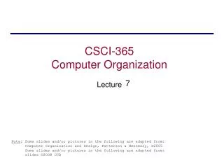
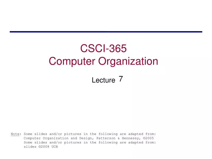
7. CSCI-365 Levels of Representation. High Level Language Program (e.g., C). lw $t0, 0($2) lw $t1, 4($2) sw $t1, 0($2) sw $t0, 4($2). temp = v[k]; v[k] = v[k+1]; v[k+1] = temp;. Compiler. Assembly Language Program (e.g.,MIPS). Assembler. Machine Language Program (MIPS).

E N D
CSCI-365 Levels of Representation High Level Language Program (e.g., C) lw $t0, 0($2) lw $t1, 4($2) sw $t1, 0($2) sw $t0, 4($2) temp = v[k]; v[k] = v[k+1]; v[k+1] = temp; Compiler Assembly Language Program (e.g.,MIPS) Assembler Machine Language Program (MIPS) 0000 1001 1100 0110 1010 1111 0101 1000 1010 1111 0101 1000 0000 1001 1100 0110 1100 0110 1010 1111 0101 1000 0000 1001 0101 1000 0000 1001 1100 0110 1010 1111 Machine Interpretation Hardware Architecture Description (e.g., block diagrams) Architecture Implementation Logic Circuit Description(Circuit Schematic Diagrams)
Recalling Register Conventions Registers and data sizes in MIPS.
Big Idea: Stored-Program Concept • Computers built on 2 key principles: 1) Instructions are represented as bit patterns - can think of these as numbers 2) Therefore, entire programs can be stored in memory to be read or written just like data • Simplifies SW/HW of computer systems: • Memory technology for data also used for programs • Programs can be written to manipulate other programs (or self?)
Consequence #n: Everything Addressed • Since all instructions and data are stored in memory, everything has a memory address: instructions, data words • both branches and jumps use these • One register keeps address of instruction being executed: “Program Counter” (PC) • Basically a pointer to memory: Intel calls it Instruction Address Pointer, a better name
Consequence #n+1: Binary Compatibility • Programs are distributed in binary form • Programs bound to specific instruction set • Different version for Macintoshes and PCs • New machines want to run old programs (“binaries”) as well as programs compiled to new instructions • Leads to “backward compatible” instruction set evolving over time • Selection of Intel 8086 in 1981 for 1st IBM PC is major reason latest PCs still use 80x86 instruction set (Pentium 4); could still run program from 1981 PC today
Instructions as Numbers • Currently all data we work with is in words (32-bit blocks): • Each register is a word • lw and sw both access memory one word at a time • So how do we represent instructions? • Remember: CPU only understands 1s and 0s, so “add $t0,$0,$0” is meaningless • MIPS wants simplicity: since data is in words, make instructions be words too
Instructions as Numbers • One word is 32 bits, so divide instruction word into “fields” • Each field tells processor something about instruction • We could define different fields for each instruction, but MIPS is based on simplicity, so define 3 basic types of instruction formats: • R-format • I-format • J-format
Instruction Formats • I-format: used for instructions with immediates, lw and sw (since the offset counts as an immediate), and the branches (beq and bne) • (but not the shift instructions; later) • J-format: used for j and jal • R-format: used for all other instructions • It will soon become clear why the instructions have been partitioned in this way
6 5 5 5 5 6 opcode rs rt rd shamt funct R-format Instructions • Define “fields” of the following number of bits each: 6 + 5 + 5 + 5 + 5 + 6 = 32 • For simplicity, each field has a name: • Important: On these slides and in book, each field is viewed as a 5- or 6-bit unsigned integer, not as part of a 32-bit integer • Consequence: 5-bit fields can represent any number 0-31, while 6-bit fields can represent any number 0-63
R-format Instructions • What do these field integer values tell us? • opcode: partially specifies what instruction it is • Note: This number is equal to 0 for all R-Format instructions • funct: combined with opcode, this number exactly specifies the instruction • Question: Why aren’t opcode and funct a single 12-bit field? • Answer: We’ll answer this later
opcode rs rt rd shamt funct R-format Instructions • rs (Source Register): generally used to specify register containing first operand • rt (Target Register): generally used to specify register containing second operand (note that name is misleading) • rd (Destination Register): generally used to specify register which will receive result of computation
R-format Instructions • Final field: • shamt: This field contains the amount a shift instruction will shift by. Shifting a 32-bit word by more than 31 is useless, so this field is only 5 bits (so it can represent the numbers 0-31) • This field is set to 0 in all but the shift instructions • For a detailed description of field usage for each instruction, see green insert in textbook • (You can bring with you to all exams)
R-format Example • MIPS Instruction: add $8,$9,$10 opcode = 0 (look up in table in book) funct = 32 (look up in table in book) rd = 8 (destination) rs = 9 (first operand) rt = 10 (second operand) shamt = 0 (not a shift)
000000 0 01001 9 01010 10 01000 8 00000 0 100000 32 hex R-format Example • MIPS Instruction: add $8,$9,$10 Decimal number per field representation: Binary number per field representation: hex representation: 012A 4020hex decimal representation: 19,546,144ten • Called a Machine Language Instruction
I-format Instructions • What about instructions with immediates? • 5-bit field only represents numbers up to the value 31: immediates may be much larger than this • Ideally, MIPS would have only one instruction format (for simplicity): unfortunately, we need to compromise • Define new instruction format that is partially consistent with R-format: • First notice that, if instruction has immediate, then it uses at most 2 registers
opcode 6 rs 5 rt 5 immediate 16 I-format Instructions • Define “fields” of the following number of bits each: 6 + 5 + 5 + 16 = 32 bits • Again, each field has a name: • Key Concept: Only one field is inconsistent with R-format. Most importantly, opcode is still in same location
opcode rs rt immediate I-format Instructions • What do these fields mean? • opcode: same as before except that, since there’s no funct field, opcode uniquely specifies an instruction in I-format • This also answers question of why R-format has two 6-bit fields to identify instruction instead of a single 12-bit field: in order to be consistent as possible with other formats while leaving as much space as possible for immediate field • rs: specifies a register operand (if there is one) • rt: specifies register which will receive result of computation (this is why it’s called the target register “rt”) or other operand for some instructions
I-format Instructions • The Immediate Field: • 16 bits can be used to represent immediate up to 216 different values • This is large enough to handle the offset in a typical lw or sw, plus a vast majority of values that will be used in the slti instruction
I-format Example • MIPS Instruction: addi $21,$22,-50 opcode = 8 (look up in table in book) rs = 22 (register containing operand) rt = 21 (target register) immediate = -50 (by default, this is decimal)
001000 8 10110 22 10101 21 1111111111001110 -50 I-format Example • MIPS Instruction: addi $21,$22,-50 Decimal/field representation: Binary/field representation: hexadecimal representation: 22D5 FFCEhex decimal representation: 584,449,998ten
Problem 1 0xAE0BFFFC, 0x8D08FFC0 What assembly instruction does the above represent? • Op=0, rs=1, rt=2, rd=3, shamt=0, funct=32 • Op=0x2B, rs=0x10, rt=0x5, const=0x4 What type instruction do the above represent? What is the MIPS assembly instruction above?
I-format Problem • Problem: • Chances are that addi, lw, sw and slti will use immediates small enough to fit in the immediate field • ...but what if it’s too big? • We need a way to deal with a 32-bit immediate in any I-format instruction
I-format Problem • Solution to Problem: • Handle it in software + new instruction • Don’t change the current instructions: instead, add a new instruction to help out • New instruction: lui register, immediate • Stands for Load Upper Immediate • Takes 16-bit immediate and puts these bits in the upper half (high order half) of the specified register • Sets lower half to 0s
I-format Problem • Solution to Problem (continued): • So how does lui help us? • Example: addi $t0, $t0, 0xABABCDCD becomes lui $at, 0xABAB ori $at, $at, 0xCDCD add $t0, $t0, $at • Now each I-format instruction has only a 16-bit immediate • Wouldn’t it be nice if the assembler would do this for us automatically? (later)
opcode rs rt immediate Branches: PC-Relative Addressing • Use I-Format • opcode specifies beq versus bne • rs and rt specify registers to compare • What can immediate specify? • Immediate is only 16 bits • PC (Program Counter) has byte address of current instruction being executed; 32-bit pointer to memory • So immediate cannot specify entire address to branch to
Branches: PC-Relative Addressing • How do we typically use branches? • Answer: if-else, while, for • Loops are generally small: usually up to 50 instructions • Function calls and unconditional jumps are done using jump instructions (j and jal), not the branches • Conclusion: may want to branch to anywhere in memory, but a branch often changes PC by a small amount
Branches: PC-Relative Addressing • Solution to branches in a 32-bit instruction: PC-Relative Addressing • Let the 16-bit immediate field be a signed two’s complement integer to be added to the PC if we take the branch • Now we can branch ± 215 bytes from the PC, which should be enough to cover almost any loop • Any ideas to further optimize this?
Branches: PC-Relative Addressing • Note: Instructions are words, so they’re word aligned (byte address is always a multiple of 4, which means it ends with 00 in binary) • So the number of bytes to add to the PC will always be a multiple of 4 • So specify the immediate in words • Now, we can branch ± 215words from the PC (or ± 217 bytes), so we can handle loops 4 times as large
Branches: PC-Relative Addressing • Branch Calculation: • If we don’t take the branch: PC = PC + 4 PC+4 = byte address of next instruction • If we do take the branch: PC = (PC + 4) + (immediate * 4) • Observations • Immediate field specifies the number of words to jump, which is simply the number of instructions to jump • Immediate field can be positive or negative • Due to hardware, add immediate to (PC+4), not to PC; will be clearer why later in course
opcode rs rt immediate Branch Example Loop: beq $9,$0,End add $8,$8,$10 addi $9,$9,-1 j Loop End: • beq branch is I-Format: opcode = 4 (look up in table) rs = 9 (first operand) rt = 0 (second operand) immediate = ???
opcode rs rt immediate Branch Example Loop: beq $9,$0,End add $8,$8,$10 addi $9,$9,-1 j Loop End: • Immediate Field: • Number of instructions to add to (or subtract from) the PC, starting at the instruction following the branch • In beq case, immediate = 3
opcode 000100 4 01001 rs 9 00000 rt 0 0000000000000011 immediate 3 Branch Example Loop: beq $9,$0,End add $8,$8,$10 addi $9,$9,-1 j Loop End: decimal representation: binary representation:
Questions on PC-addressing • Does the value in branch field change if we move the code? • What do we do if destination is > 215 instructions away from branch?
J-format Instructions • For branches, we assumed that we won’t want to branch too far, so we can specify change in PC • For general jumps (j and jal), we may jump to anywhere in memory • Ideally, we could specify a 32-bit memory address to jump to • Unfortunately, we can’t fit both a 6-bit opcode and a 32-bit address into a single 32-bit word, so we compromise
6 bits opcode target address 26 bits J-format Instructions • Define “fields” of the following number of bits each: • As usual, each field has a name: • Key Concepts • Keep opcode field identical to R-format and I-format for consistency • Combine all other fields to make room for large target address
Target Addressing Example • Loop code from earlier example • Assume Loop at location 80000
Branching Far Away • If branch target is too far to encode with 16-bit offset, assembler rewrites the code • Example beq $s0,$s1, L1 ↓ bne $s0,$s1, L2 j L1L2: …
Problem 2 We explore 32-bit constants in MIPS: 1010 1101 0001 0000 0000 0000 0000 0010 1111 1111 1111 1111 1111 1111 1111 1111 • Write the MIPS code that creates the 32-bit constants listed above and stores that value to $t1. • If the current value of the PC is 0x00000000, can you use a single jump instruction to get to the PC address as shown above. • If the current value of the PC is 0x00000600, can you use a single branch instruction to get to the PC address shown above
Character Data §2.9 Communicating with People • Byte-encoded character sets • ASCII: 128 characters • 95 graphic, 33 control • Latin-1: 256 characters • ASCII, +96 more graphic characters • Unicode: 32-bit character set • Used in Java, C++ wide characters, … • Most of the world’s alphabets, plus symbols • UTF-8, UTF-16: variable-length encodings
Byte/Halfword Operations • Could use bitwise operations • MIPS byte/halfword load/store • String processing is a common case lb rt, offset(rs) lh rt, offset(rs) • Sign extend to 32 bits in rt lbu rt, offset(rs) lhu rt, offset(rs) • Zero extend to 32 bits in rt sb rt, offset(rs) sh rt, offset(rs) • Store just rightmost byte/halfword
Problem 3 Assume that the register $t1 contains the address 0x1000 0000 and the register $t2 contains the address 0x1000 0010 • lb $t0, 0($t1) • sw $t0, 0($t2) • lb $t0, 0($t1) • sb $t0, 0($t2) • Assume that the data in hex at address 0x1000 0000 is • 1000 0000 12 34 56 78 • What value is stored at the address pointed to by register $t2? Assume the memory location pointed to $t2 initialized to 0xFFFF FFFF.
String Copy Example • C code (naïve): • Null-terminated string void strcpy (char x[], char y[]){ int i; i = 0; while ((x[i]=y[i])!='\0') i += 1;} • Addresses of x, y in $a0, $a1 • i in $s0
String Copy Example • MIPS code: strcpy: addi $sp, $sp, -4 # adjust stack for 1 item sw $s0, 0($sp) # save $s0 add $s0, $zero, $zero # i = 0L1: add $t1, $s0, $a1 # addr of y[i] in $t1 lbu $t2, 0($t1) # $t2 = y[i] add $t3, $s0, $a0 # addr of x[i] in $t3 sb $t2, 0($t3) # x[i] = y[i] beq $t2, $zero, L2 # exit loop if y[i] == 0 addi $s0, $s0, 1 # i = i + 1 j L1 # next iteration of loopL2: lw $s0, 0($sp) # restore saved $s0 addi $sp, $sp, 4 # pop 1 item from stack jr $ra # and return