Download
1 / 38
400 likes | 633 Views
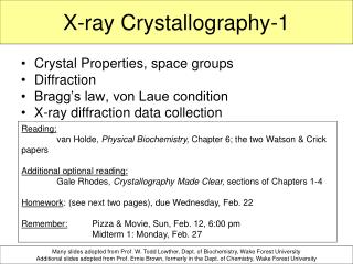
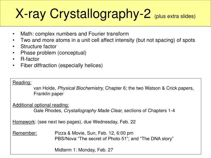
X-ray Crystallography-2 (plus extra slides). Math: complex numbers and Fourier transform Two and more atoms in a unit cell affect intensity (but not spacing) of spots Structure factor Phase problem (conceptual) R-factor Fiber diffraction (especially helices). Reading:

E N D
X-ray Crystallography-2 (plus extra slides) • Math: complex numbers and Fourier transform • Two and more atoms in a unit cell affect intensity (but not spacing) of spots • Structure factor • Phase problem (conceptual) • R-factor • Fiber diffraction (especially helices) Reading: van Holde, Physical Biochemistry, Chapter 6; the two Watson & Crick papers, Franklin paper Additional optional reading: Gale Rhodes, Crystallography Made Clear, sections of Chapters 1-4 Homework: (see next two pages), due Wednesday, Feb. 22 Remember: Pizza & Movie, Sun, Feb. 12, 6:00 pm PBS/Nova “The secret of Photo 51”; and “The DNA story” Midterm 1: Monday, Feb. 27
Homework 4 (Chapter 6, X-ray diffraction), due Wednesday, Feb. 22 • If not stated otherwise, assume l = 0.154 nm (CuKa-radiation) • van Holde 6.1 • van Holde 6.2a (Hint: put one atom at x, y, z, the other atom at x+1/2, -y, -z) • van Holde 6.3 • NaCl crystals are crushed and the resulting microcrystalline powder is placed in the X-ray beam. A flat sheet of film is placed 6.0 cm from the sample and exposed. Ignoring the possibility of forbidden reflections (which is in fact the case with NaCl, because the lattice is centered), what would be the diameters and indices of the first two (innermost) rings on the photograph? NaCl is cubic with unit cell dimension a = 0.56nm. • You are working with a linear crystal of atoms, each spaced 6.28 nm apart. You adjust your x-ray emitter so that it emits 0.628 nm x-rays along the axis of the array. • As we did in class, using the reciprocal lattice and the sphere of reflection, draw the allowed S vectors (S = k - k0). Denote the direction of propagation of the incoming x-rays as the positive x-axis. (k0 is direction of incoming X-rays, S is scattering vector). • You place a 1 cm2spherical detector 1 cm from the sample, centered on the x-axis, on the opposite side of the emitter. Draw the pattern you expect to detect. Clearly mark the expected distances. • If you performed the experiment on a linear crystal with atoms spaced 0.1 nm apart, what pattern would you detect? Would you have the same pattern if your detector were 1 m2? What does this say about the resolution of your experiment? • … continued on next page
Homework 4 (Chapter 6, X-ray diffraction), due Wednesday, Feb. 22: • … continued • If not stated otherwise, assume l = 0.154 nm (CuKa-radiation) • van Holde 6.6 a-c (Fig. 6.18, don’t need to do 6d) • van Holde 6.9 a-c (in c), real space means on film) • van Holde 6.9 d but: Sketch the fiber diffraction pattern expected for A-DNA (not Z-DNA).
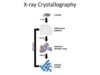
So far… Bragg’s law and von Laue’s law:By observing the spacing and pattern of reflections (spots) on the diffraction pattern, we can determine the lengths, and angles between each side of the unit cell, as well as the symmetry or space group (from systematic absences) How do we find out what’s inside the unit cell? (i.e. the interesting stuff, like proteins). The intensity of the spots (square of structure factor) ‘tells us what’s inside a unit cell.’
Example: Two atoms in a unit cell (white board example) Let’s look at two atoms in a unit cell, that are a distance r1 and r2 from the origin. After hit by an incoming X-ray, they both emit a wave. E2 wave is shifted by a phase factor, f. f = 2pDr/l is phase difference between the two waves. Point: The intensity of the wave, I = |E|2, depends on f, which, in turn, depends on the wave-vector (scattering direction) and location of the atoms in the unit cell.
The intensity of the spots, I, is equal to the square of the electric field of the wave, E. As shown for two atoms, E depends on the spacing (coordinates) and number of atoms, and the scattering direction, Diffraction pattern for T4 lysozyme crystal So, if we have two or more atoms in a unit cell, the intensity of the spots, I, depends on the spacing (coordinates) and number of atoms, and the scattering direction, We have a relationship between atomic coordinates, (which we want to know) and the intensity of the spots (which we can measure).
Solving macromolecular structures by X-ray diffraction • If we have two or more atoms in a unit cell, the intensity of the spots changes the diffraction angle q is not affected by the number of atoms in a unit cell. The diffraction angle is still only related to the unit cell dimension by Bragg’s law. • However, with one atom, the phase and amplitude of the resultant wave from each plane (atom) was the same. With more than one atom, the phase and amplitude coming from each plane of different atoms may be different, resulting in different intensities of the reflections. • Deconvolute each reflection into the phase and amplitude contributions from each of the individual reflections from each atom in the molecule. # of atoms in unit cell does NOT affect reflection angle (Bragg’s law). # of atoms (electron density) in unit cell DOES affect intensity of reflection spots.
The structure factor, F (hkl) Structure Factor for many atoms inside unit cell: Diffraction pattern for T4 lysozyme crystal • F (hkl) is electric field amplitude for a certain scattering direction (reflection spot h,k,l on film) • x, y, z … fractional coordinates describing the position of each atom inside unit cell. • fj is the amplitude of the electric field coming from each atom j inside unit cell (amplitude is proportional to electron density). • The sum is over all N atoms inside a unit cell. • S = (ha*, kb* lc*) is the scattering vector for each diffraction spot
Moving from fixed points to electron density inside a cell: • The sum is replaced by an integral over the volume of the unit cell, V. • the amplitude fi is replaced by the electron density r(r) (the more density the larger the amplitude). This is very nice now: If we know the electron density r(r) (i.e. positions of atoms) inside unit cell, we can predict the intensity, of each reflection spot (h, k, l) on the film Knowing the size of the unit cell, and knowing the electron density, we can calculate (predict) the location and intensity of each diffraction spot.
The phase of the structure factor • The structure factor (a complex number) has a magnitude |(F(hkl)| and a “phase angle” ahkl.
Example You know that an orthorhombic unit cell has two atoms at 1/12, 1/12, 1/12 and -1/12, 1/12, 1/12 (fractional coordinates). If these are the only unique atom in the unit cell, calculate the structure factor F (hkl) and the phase angle ahkl for the h=1, k=1, l=0 reflection. What is the intensity of that spot, compared to possible maximum intensity? (Assume fj for each atom is 1) Important subpoint: If we know the position and type of all atoms in the unit cell, we can calculate F(hkl), magnitude and phase.
Starting with the equation for the structure factor F(hkl), show that the intensity of reflections along the (h00) axis will be zero for all odd values of h, when a two-fold screw axis is aligned along the crystallographic a-axis. h = 4 h = 3 a2 h = 2 a a h = 1 h = 0 h = -1 h = -2 h = -3 h = -4 k = l = 0
Moving from the structure factor to the electron density (final goal). • We need to do the ‘Fourier transform’ of the structure factor to get the electron density out. Now, the diffraction pattern is actually made up of points, so the integral becomes a sum (Fourier series) over all diffraction spots: And that is what we want!!
… but wait, there is a problem…the phase problem • We cannot measure F(hkl) (complex number), only |F(hkl)|. • We can measure the intensity I(hkl) of the spots We only know the magnitude but not the direction (phase angle a) of F(S). We have lost the phase. How bad is that? Pretty bad, because we can calculate the “magnitude” of the electron density, but we don’t know where it is in the unit cell. What can we do??
Electron density calculated from the two components of F(hkl). • Using only |F(hkl)|. The map does not fit the actual structure (like a Patterson map (see next)). • Using only the phase information ([F(hkl)] was set to 1).
Phase problem solutions • Molecular replacement: • If we are lucky, you can get hold of the structure of a known, isomorphous crystal. • This is often used when one wants to know the effect of a mutation in a crystal, or when one wants to know where a substrate binds (soak substrate into crystal). • We use the structure (r (r)) of the known crystal as a starting point. • Iterative solution: Make small changes to known structure (r(r)), calculate new diffraction pattern (I(hkl), compare to data (diffraction pattern of new crystal), adjust known structure (r(r)), again, calculate new diffraction pattern (I(hkl)), compare with data,… etc.
Multiple Isomorphous Replacement • Collect the diffraction data from native crystal. • Soak in a heavy atom and collect diffraction data. • By comparing those two data sets, the position and phase of the heavy metals can often be figured out (because they are very strong scatterers). • Repeat with other heavy atom derivatives. • These data sets can then be used to estimate the phases of the native data set. • Do iterative improvements (estimate position and phases, calculate diffraction spots, compare with data, estimate improved positions and phases, calculate diffraction spots, etc…)
Structure refinement, the R-factor • The R-factor is defined as: • |F (hkl)| is from measured intensity, Fcalc is calculated structure factor • It’s the error between the real diffraction pattern and the calculated one. • A R-factor of ~0.2 (20% error) is considered good enough to give a good model of the structure.
Example The precession photograph in Fig. 6.18 was recorded with a crystal to film distance of 7.65 cm and the spacing between reflections was measured to be 0.15 cm. The third dimension for this crystal is 3.777 nm. • Calculate the unit cell dimensions of this crystal. • Propose one possible space group for this crystal. • If the third axis has 41 symmetry, what systematic absences would you expect to see?
Fiber diffraction • If there is inherent symmetry in a molecule (i.e. long helical biopolymers) X-Ray diffraction patterns can be obtained from non-crystalline samples. • Like one-dimensional crystal along helix axis. • We can treat an exact repeat of helix (i.e. one residue) as a crystalline unit cell. • Can get information about helical symmetry, pitch and radius. • Meridianal reflections: information on pitch and symmetry • Equatorial reflections: radius of helix
Distinguish between continuous and discontinuous helix Pitch P Rise h Radius rh c… repeat Continuous helix Discontinuous helix Continuous: “line wrapped around a cylinder, Discontinuous: has m residues per turn
Cylindrical unit cell in real and reciprocal space Position in real space Scattering vector in reciprocal space The Fiber Unit Cell • Describe unit cell in cylindrical coordinates. • Real lattice: cylindrical coordinates (z, r, f) • Reciprocal lattice: coordinates (Z, R, Ψ)
The structure factor in cylindrical coordinates • Now, we’ll assume a continuous helix: • Helix is a line wrapped around a cylinder (r is zero if not on line) • Unit cell has a length equal to the pitch of helix.
The structure factor for continuous helix • Jn(x), Bessel functions The intensity I ~ Jn2 • I-n(x) = In(x), In(-x) = In(x) • Symmetric about n and x • Get x-shaped diffraction pattern
Diffraction pattern for continuous helix • We get spots on layer lines that are 1/P apart. P is pitch. Each layer line corresponds to a Bessel function for n = 1, 2, 3, …. Lines at Z = n/P • We get points on those layer lines that correspond to the maxima of the Bessel functions. • This results in a X-pattern. • Maxima of J1 @ x = 1.85
Diffraction pattern for discontinuous helixwith integral number of m residues, per repeat c. • The X-pattern we got for the continuous helix will just repeat itself on the Z-axis with spacing Z=c/P • Examples: • B-DNA: c = 10 residues/turn • A-DNA: c = 11 residues/turn • 310-helix: c = 3 residues/turn • Each layer line is still spaced at 1/P • The pattern is repeated at Z = c/P = 1/h
Radius determination from diffraction pattern Maxima along equatorial line (n=0) result from hexagonal crystal packing of unit cells. Spacing of spots along equatorial line is:
Diffraction Pattern or B-DNA In May 1952, Rosalind Franklin took beautiful X-ray diffraction patterns of pictures of B-form DNA . The X-pattern is indicative of a helix!! The bases are 0.34 nm apart; there are ten nucleotides per turn; each turn has a rise of 3.4 nm; the diameter of the helix is 2 nm. This pattern is consistent with the model that Watson and Crick built.
Extra material • Reciprocal space, Bragg’s law and Ewaldshere.
Reciprocal lattice Real lattice Reciprocal lattice
Relationship between unit cell parameters in real space and in reciprocal space Stout & Jensen (1989) X-Structure Determination. A practical guide. 2nd ed. John Wiley & Sons, New York
Examples of direct and reciprocal lattices (Figures from Jensen and Stout “X-Ray structure determination. A pratical guide” Orthorhombic direct and reciprocal cells
Reciprocal lattice X-ray beam 1/l A Sphere of reflection (Ewald sphere) 2q B q L Visualization of Bragg’s law O
Visualization of Bragg’s law Reciprocal lattice X-ray beam O Sphere of reflection (Ewald sphere) Rotating beam (or crystal) we get reflections from all points within sphere.
Scattering direction k Sphere of reflection in 3D reciprocal space 2qhkl Shkl
Definition of reciprocal lattice (hand out)Bragg’s law in reciprocal space Von Laue condition in reciprocal space (orthogonal lattices): Von Laue condition in reciprocal space for all crystal symmetries:
q = 110° “Resolution in X-Ray Crystallography” There are several issues: • Theoretical limit: smallest d in Bragg’s law, 2sinq = l/d, dhkl, min ~0.094 nm for CuKa-radiation (l = 0.154 nm) and largest practical angle 2q = 110° (good: can get atomic resolution, ~ 1Å) • The “resolution” of X-ray diffraction is also limited by being able to separate spots on film. Reflection spots must be separated by at least 2° (because of their own size, ~ 1° at half-height). 2sinq = l/dunit cell. For larger unit cells, need to use larger l (CuKa over MoKa). • How many data points (reflections) are required to obtain atomic resolution? We need (at least) 4N equations to solve for 4N parameters (x, y, z and temperature factor B for each of the N atoms within unit cell). Need at least 4N good reflection spots on film. Need at least 4N reciprocal lattice points inside sphere of reflection. # of points inside limiting sphere: Where d is resolution; N # of reflections needed for that resolution; Vreal is volume of real lattice.
# of unique reflections on film • If we get N* reflections on film, some of them are redundant because of symmetry. • Friedel’s law: I(hkl) = I(–h –k –l) • Each symmetry operator reduces # of unique reflections (For P212121, only 1/8 the reflections are unique). • Good news: because of symmetry, not the whole unit cell needs to be solved.