Download
1 / 13
140 likes | 220 Views
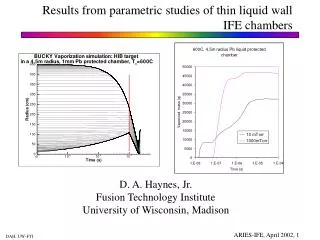
Views on Neutronics and Activation Issues Facing Liquid-Protected IFE Chambers. L. El-Guebaly and the ARIES Team Fusion Technology Institute University of Wisconsin - Madison 16 th TOFE Meeting September 14-16, 2004 Madison, WI. Objectives .

E N D
Views on Neutronics and Activation Issues Facing Liquid-Protected IFE Chambers L. El-Guebaly and the ARIES Team Fusion Technology Institute University of Wisconsin - Madison 16th TOFE Meeting September 14-16, 2004 Madison, WI
Objectives • Develop design space and operational windows for ARIES-IFE-HIB (no point design). • Concerns: • Breeding potential of candidate breeders: Flibe & Flinabe • Ability of liquid wall to protectstructure for 40 FPY • Activation level of structural components: shield & nozzles • Isochoric heating problems • Effect of radiation damage and cyclic fatigue on structure lifetime.
3 m Radius | | | Nozzles FS Shield (90% FS, 10% Liquid) 0.5 m Radius | Liquid Blanket Jets (58% Liquid, 42% void) Gap Target Schematic of Radial Build • Flibe (BeF2,(LiF)2) and Flinabe (NaF, LiF, BeF2) with natural Li. • ODS FS(preferred structure) or 304-SS. • Innermost layer of shield represents nozzles and feeding tubes. • Point source and 1-D spherical geometry.
Key ARIES-IFE-HIB Parameters Target yield 460 MJ Rep rate 4 Hz # of pulses 126 million/FPY Average source neutron energy 11.8 MeV Penetrations coverage 3% Plant lifetime 40 FPY Availability 85%
ARIES-IFE Requirements and Design Limits Overall TBR ≥ 1.08 dpa* to structure ≤ 200 dpa for FS ≤ 25 dpa for 304-SS Heproduction for reweldability of FS ≤ 1 He appm WDR for Class C low level waste ≤ 1 ___________________ * Cyclic fatigue could be more restrictive life-limiting factor than radiation damage.
Flibe Breeds more Tritium than Flinabe • 85 cm thick Flibe and 150 cm thick Flinabe meet breeding requirement. • Enrichment does not enhance breeding of thick Flinabe. • Nuclear energy multiplication amounts to ~1.25.
Flibe has Slightly Better Shielding Performance than Flinabe • 85 cm Flibe blanket meets 200 dpa limit for advanced FS only. • 1.5 m Flinabe meets dpa limits for both structures.
Excessive Helium Production at Chamber Structure Problem: Innermost layer of shield and nozzles cannot be rewelded at any time during operation.
Steel Composition(in wt%) ODS M-F82H-FS* 304-SS# Fe 87.891 70.578 C 0.04 0.046 N 0.005 0.038 O 0.13 – Si 0.24 0.47 P 0.005 0.026 S 0.002 0.012 Ti 0.09 0.03 V 0.29 – Cr 8.7 17.7 Mn 0.45 1.17 Co 0.0028 0.1 Ni 0.0474 9.3 Cu 0.01 0.2 Nb 0.00033 – Mo 0.0021 0.33 Ta 0.08 – W 2 – Y 0.7 – _____________________________________________________ * IEA Modified F82H FS + 0.25wt% Y2O3, per M. Billone (ANL). Other elements include: B, Al, As, Pd, Ag, Cd, Sn, Sb, Os, Ir, Bi, Eu, Tb, Dy, Ho, Er, U. # C. Baker et al., "Starfire-A Commercial Tokamak Fusion Power Plant Study," Argonne National Laboratory Report, ANL/FPP-80-1 (1980).
All Steel Alloys Generate High Level Waste Flinabe System Flibe System • 304-SS generates very high level waste. • Main contributors to WDR: 94Nb (from Nb),99Tc (from Mo), and 192nIr (from W).
Potential Solutions for Waste Problem • Thicken blanket and deplete Flibe/Flinabe (cost?), • Average WDR over thicker shield (> 50 cm), • Control Mo and Nb for Flibe system in particular (cost?). • In practice, Mo and Nb impurities cannot be zeroed out. Actual level depends on $/kg to keep Mo and Nb << 1 wppm. • Nozzles generate high level waste unless mixed with shield and disposed as single unit at end of life.
Isochoric Heating • FS temperature fluctuates 4 times per second. • Nuclear heating will induce stresses on the order of 10 MPa in FS • Fatigue from cycling and repetitive shock wave could: • Cause internal cracks • Shorten structure life • When combined with radiation damage, fatigue life could be more restrictive than 200 dpa limit. 0.25 s
Concluding Remarks • No breeding problem identified for Flibe and Flinabe. • Excessive helium production at structure precluding FS reweldability during operation. • Steel-based structure produces high level waste (WDR >> 1), mandating: • – Thicker blanket with depleted lithium (cost ?) • – Shield > 50 cm thick, and/or • – Nb and Mo impurity control (cost?). • Nozzles need additional protection to qualify as low level waste unless mixed and disposed with shield. • Combined effect of radiation damage and fatigue on structure lifetime should be addressed in future studies.