Download
1 / 47
470 likes | 478 Views
Producing An Image. Lavin: Chapter 6 CTVT: 529-532. To review…. Elements & electrons – Structure & what happens when they become unstable The electromagnetic spectrum – Which waves penetrate farther? Shorter or longer wavelength? Electrification & induction

E N D
Producing An Image Lavin: Chapter 6 CTVT: 529-532
To review… • Elements & electrons – • Structure & what happens when they become unstable • The electromagnetic spectrum – • Which waves penetrate farther? Shorter or longer wavelength? • Electrification & induction • Induction uses force fields to cause a reaction without contact • The parts of the x-ray unit • Functions & safety measures • Creating images on film • Cassettes, screens, and film
To review… • What do we mean by the “image receptor” in film-based processing? • What 3 main components make up the receptor?
Producing Radiographs The image receptor receives the produced x-rays and produces the actual image. Receptor components in film-based imaging: • Cassette/film holder • Intensifying Screen • Film
To review… What within the image receptor can cause a reduction in sharpness on the radiograph?
In review… Regarding the cassette itself, discuss: • Handling – both open & closed • How to open • How to get the film out • How to reload • Cleaning
In review… What are some examples of lead blockers, and how are they used in radiography?
In Review… What is an intensifying screen, and what is its purpose in film-based processing?
Intensifying Screens • Purpose: • Reduces the amount of radiation required • Only 5% of exposure results from ionization of x-rays. The remainder is due to light emitted from intensifying screens. • Reduces mAs needed • Decreases radiation dose to the patient • Decreases exposure potential to the technician • Enhances contrast • The screens in an x-ray cassette sandwich the film.
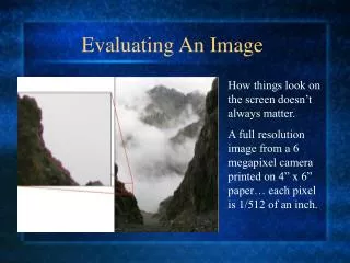
Producing an Image “The main objective of all imaging systems is to demonstrate the differences in tissue density.”
Learning Objectives: Chapter 6 • List & understand the 4 factors of radiographic exposure and how each impacts the production of a diagnostic image. • Kilovoltage (kV), milliamperes (mA), time (seconds), distance • Understand how milliamperage (quantity) and kilovoltage (quality) of x-rays can impact a radiograph • Define scatter radiation and understand its impact on radiographic quality and radiation exposure of personnel. • Define the 15% rule, and be able to use it to fine-tune a radiographic image. • Understand how to create and use a technique chart to create diagnostic radiographs.
The Four Factors of Radiographic Exposure These must be manipulated so tissue absorption of radiation is exactly correct to demonstrate anatomy/pathology and minimize artifacts. The 4 factors: • Kilovoltage (kV) – “quality” or contrast • Milliamperes (mA) – “quantity” or darkness • Time (seconds) – exposure time • Distance
1st Factor of Radiographic Exposure: Kilovoltage • Kilovoltage Peak (kVp) - the maximum value of x-ray tube voltage during x-ray production • Quality of the x-rays • Directs x-ray penetration • Increase = Increase in contrast • More contrast = • Darks vs lights • Fewer shades of gray in-between • Can distinguish between structures • Can impact density, since too high will darken film
Technical Factors of Exposure • kVp = Power behind the cue stick • Ma = Number of balls in play Energy is transferred as balls bounce off each other
Optimizing Kilovoltage • Use the lowest setting that will penetrate region of interest, enhance tissue contrast, and minimize scatter radiation. • Kilovoltage is energy, so not directly proportionate to tissue thickness • Tissue Fluence - Variations in tissue absorption • Calculate a starting point, but be ready to adjust • Changing a setting doesn’t yield a proportional result
What is Scatter Radiation? • “Secondary radiation” • Lower-energy x-ray photons that have undergone a change in direction after interacting with structures in a patient’s body • Is of concern because: • Decreases image quality • Increases radiation exposure • The primary source of exposure for technicians • Darkens radiograph & decreases contrast
Managing Scatter Radiation • Is directly impacted by increases in: • Kilovoltage • Thickness of the part being radiographed • Size of the field • Can be managed by: • Reducing kVp’s as low as possible • Careful collimation • Avoiding retakes • Use of a grid
Optimizing Kilovoltage The 15% Rule – A “rule of thumb” • Used to optimize kV’s and enhance contrast • Doesn’t impact density • To increase penetration – increase kV’s 15% • To decrease penetration – decrease kV’s by 15% Don’t forget to adjust mA’s if you change kVp’s: • Increasing kV = Divide mA’s by 2 • Decreasing kV = Multiply mA’s by 2 “The power behind the cue stick”
Adjusting kVp’s Not enough Contrast Optimized Contrast
2nd Factor of Radiographic Exposure: Milliamperage • mA • “Quantity” of X-Rays – How many • Impacts density or darkness • Directly proportional – doubling doubles density • A very simple concept
Advantages of high mA • Allows for shorter time setting with the same number of x-rays produced • Shorter time = possibility of motion is decreased • Decreases exposure for restraining personnel • More x-rays produced • Allows for examination of thicker anatomic areas “Increases the number of balls in play”
3rd Factor of radiographic Exposure: Time (mA’s) • Adds in time factor • mA X seconds = mAs • Suitable mA setting depends on the thickness and type of tissue being radiographed • mA & time are inversely related – but often combined settings on the x-ray machine • Changes in mAs: • Increased = x-ray becomes blacker in color overall • Decreased = x-ray becomes lighter in color overall
Troubleshooting Technical Factors If image isn’t coming out right: • Reposition & re-measure • Adjust mA’s first, as long as tissue is penetrated • An easy change to make & measure… • Adjust kVp’s using 15% rule • If film is light, check temperature of chemicals • If image is dull gray, look for light leaks in darkroom or improperly exposed film in box • Have the unit serviced & recalibrated
4th Factor of Radiographic Exposure: Distance • Distance: • The Inverse Square Law • The intensity of radiation at a location is inversely proportional to the square of its distance from the radiation source In most clinics, the distance between the x-ray tube and receptor/cassette is fixed at 40 inches.
Anatomic Considerations • Skull & Cervical Spine • High contrast bone & tissue – higher kVp’s not required • Chest, thorax, abdomen • Homogeneous density, so scatter possible if high kVp’s used • Keep KVp’s as low as possible and increase mA’s • Extremities • Body parts thin, and tissue-to-bone ratio high • Low kVp’s indicated • Birds & pocket pets • Similar technical factors to extremities
Evaluating Radiographs • The technician needs to have the ability to properly evaluate a radiograph. • If you don’t know what’s good, then it will be hard to attain a good quality image on film. • Will help to minimize re-takes
Assessing a Radiograph • Taking a second radiograph is sometimes unavoidable. • If you can figure out what’s wrong, you can make corrections so that the second attempt is the last attempt. • Radiographic quality depends on the technologist’s understanding of the concepts and variables that produce a good radiograph.
Exposure Factors & X-Ray Generation X-ray generation: • mAs (current) is applied to the filament in the cathode. • mAs control the quantity/total number of x-rays • Generates an electron “space cloud” • The electrons are directed to the anode target by kVp’s. • kVp’s control the quality/penetration of x-rays • The collision produces heat and x-radiation.
Viewing a Radiograph • Viewed on an evenly lit view box in a semi-darkened room. • View box should be clean, and all light bulbs should be in working order.
Film View Position Film position on the illuminator matters: • V/D or D/V: • Head at the top of the view screen • Handshaking position • Lateral: • Head at viewer’s left • Spine on top • Limbs: • Proximal end up
Evaluation of Radiographic Technique Two basic questions… • Is the film too light or too dark? • More exposure = blacker film overall • Increase kVp or mAsto darken • Decrease kVp or mAs to lighten • Is there proper penetration/differentiation? • If cannot see contrast between structures… • Adjust kVp’s
Is there proper penetration? • If there is inappropriate penetration of the x-rays, change kVp’s • If film is dark, should be decreased. • If film is light, should be increased. • If penetration of x-radiation is satisfactory, then mAs should be adjusted.
If film is too light Is the film under penetrated? • If no: Increase mAs 30-50% • If yes: Increase the kVp 10-15% Is the film over penetrated? • If yes: Decrease kVp by 10-15% • If no: Decrease mAs by 30-50%.
What Determines Adequate Penetration? • Abdominal radiograph: • Can see outlines of liver, spleen, kidneys and bowel • Thoracic: • Heart clearly outlined, diaphragm boundary evident, bone differentiation clear • Inadequate penetration = areas almost completely white, and organs/bones cannot distinguished.
Radiograph Too Dark • If bone tissue is gray, with too little contrast between the bone and adjacent soft tissue, there was too much penetration. • Decrease kVp by 10-15% • If bone tissue is relatively white, compared to surrounding tissues, then penetration is adequate. • Decrease mAs 30-50% ***Evaluating radiographs is an art, and often several changes can be made to improve the radiograph equally***
Creating a Technique Chart Provides suggested techniques of anatomy and positioning… Without it, new calculations would have to be taken before every radiograph.
Creating a Technique Chart Step 1: Prepare • Service your processor and ensure screens and film match. • Select a medium-sized dog of average weight. Step 2: Select your mAs • Use the following for an average speed intensifying screen: • Extremity 2.5 mAs • Thorax 5 mAs • Abdomen 7.5 mAs • Spine 10 mAs Remember: mA * secs = mAs
Creating a Technique Chart Step 2: Select your mAs (cont.) • To achieve this mAs, the mA and time need to be set separately, and the machine will calculate the mAs for you. • Use these as standard mA settings: • Extremity 150 mA • Other 300 mA • Calculate the time as follows: • Extremity: 150mA X 1/60 secs (approx) = 2.5 mAs • Thorax: 300 mA X 1/60 secs = 5 mAs • Abdomen: 300 mA X 1/40 secs = 7.5 mAs • Spine: 300 mA X 1/30 secs = 10 mAs
Creating a Technique Chart Step 3: Select your initial kVp • Calculate initial kVp using Sante’s Rule • Formula: 2 x thickness + 40 + grid factor • If a grid is used, add 10 to total • Grid is usually indicated for measurements > 9 cms • Example: Body Part = 8 cms • (2 X 8) + 40 = 56 kVp • No grid necessary since < 9 cms ** Note: At VTI, we always use a grid for cats, and sometimes will use a grid as a way to achieve a clearer image, even if the animal is small **
Sante’s Rule: Why 40? • Represents the distance from the x-ray tube focal spot to the image receptor (film) in inches • This distance can be referred to as the Focal Film Distance (FFD) or Source-image Distance (SID).
Creating a Technique Chart Step 4: Expose the perfect film • Use the exposure factors calculated above as a starting point • If you can’t see details of internal structures because the image is too dark, the radiograph has been over-penetrated (too much contrast), so decrease kVp by 15% • If you can’t see details of internal structures because the image is too light, the radiograph has been under-penetrated, so increase kVp by 15% • Once the radiograph is close to perfect, reduce the changes to 5% increments until you’re satisfied with the result. • mAs can be adjusted up or down 50% as needed to alter density • Once the exposure is right, go to step 5
Creating a Technique Chart Step 5: Make the technique chart • Complete kVp’s above and below the “perfect entry” as follows: • Subtract 2 kVp from the original kVp for each cm decrease from the original • Add 2 kVp to the original kVp for each cm increase from the original kVp up to 80 kVp. • Add 3 kVp for each cm increase that places the kVp above 80 and up to 100 • Add 4 kVp for each cm increase that places the kVp above 100 Step 6: Create a Technique Chart for each different study (abdomen, thorax, extremity, and spine) • Create an additional chart for body parts that may need to be radiographed using a grid (all but extremities)
For example… In this example, the perfect combination of kVp and mAs for a sample 15 cm abdomen is shown in pink…The entries above and below are filled in based on the previous rules.
Technique Chart Homework • Create a Technique Chart for each of the following: • Extremity – No grid • Thorax – Grid • Abdomen – No grid • Spine – Grid • Use the handout and previous slides