Download
1 / 23
230 likes | 373 Views
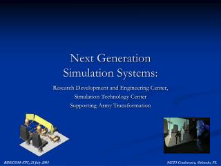
PDE 2005 The 7th NASA-ESA Workshop on Product Data Exchange (PDE) April 19-22, 2005 Manufacturing Research Center, Georgia Tech, Atlanta. AkroMetrix. Next Generation Simulation-based Design Technologies for Electronics Product Realization.

E N D
PDE 2005The 7th NASA-ESA Workshop on Product Data Exchange (PDE) April 19-22, 2005 Manufacturing Research Center, Georgia Tech, Atlanta AkroMetrix Next Generation Simulation-based Design Technologies for Electronics Product Realization Manas Bajaj1, Russell Peak1, Dirk Zwemer2, Thomas Thurman3, Michael Dickerson4, Kevin Brady5, John Messina5 1. Georgia Institute of Technology 2. AkroMetrix, LLC 3. Rockwell Collins, Inc. 4. InterCAX, LLC 5. National Institute of Standards and Technology
AbstractNext Generation Simulation-based Design Technologies for Electronics Product Realization The realm of electronics product realization is marked by an extremely fast-paced market, stringent demands for product reliability and high importance to innovative design. Further, the time-to-market and the cost-to-realize play a critical role for product success. However, these attributes pose conflicting constraints on the realization process. While engineers need to converge quickly on a set of design alternatives, the high demand for reliability increases the breadth of behavioral simulations across the design space. Further, the multi-disciplinary nature poses integration challenges due to a disparate set of engineering tools, model representations, and simulation techniques. In this presentation, we shall focus on the following three technical areas to alleviate these hurdles in knowledge management during electronics product realization: (1) Design-Analysis Integration: In order to quickly converge on a set of feasible design alternatives while covering a wide range of behavioral simulations across the design space, it is essential for engineers to synthesize analysis and solution-specific product models for a given design alternative. This process is guided by ascertaining the context of analysis, identifying possible idealizations and mapping information from design specifications to the analysis specifications. Further, the modularity of this process is essential to explore all possible alternatives. We leverage from over a decade’s worth of experience spanning methodologies and tools (www.eislab.gatech.edu/research/dai/) and some recent advances in this area to demonstrate current and envisioned technologies for seamless design-analysis integration. (2) Standards-based Knowledge Representation: In order to create high-fidelity design, analysis and manufacturable product models, it is essential to use a detailed and standard ontology for electronics product data specification. In this light, we employ STEP AP 210 (www.ap210.org) for electronic assembly packaging and design as the underlying representational structure for creating and archiving product models. Further, we use a harmonized set of STEP-based schemas for product model specifications across the design-analysis integration bridge. In this presentation, we shall focus on the ability of a standards-based knowledge representation scheme to support product and process related knowledge for electronics PLM. (3) Experimental Validation of Simulation Techniques: In general, a simulation-based methodology needs to be validated against experimental results to justify reuse and instill confidence in decisions based on simulation results. In this presentation, we shall also demonstrate on algorithmic techniques for validating simulation results with experimental data and discuss some critical issues concerning the same. Further, in this presentation, we will exemplify recent developments in the three technical areas using thermo-mechanical warpage analysis problem for printed circuit boards and assemblies, as part of the current collaborative effort between co-author organizations. http://eislab.gatech.edu/pubs/seminars-etc/2005-cpda-dsfw-peak/ This document may identify commercial product names and materials to describe certain procedures or to provide concrete examples (i.e., to help clarify abstract concepts via specific instances). In no case does product or material identification imply recommendation or endorsement by the authors or their organizations, nor does it imply that such items are necessarily the best available for the purpose. Company, product, or service names may be included that are trademarks or service marks of others.
Contents • Role of Simulation-based Design in Electronics Product Realization Theme -- Warpage Worthiness • Enabling Technologies • Design-Analysis Integration • Standards-based Product and Process Models • Computer-based engineering framework for analysis, validation and design enrichment • Future Research
Electronics Product Realization Doc/Proc/Reg Guidelines Layout Requirements Design Part Symbol & Footprint Functional Learn today Utilize tomorrow Placement Routing Review Corrections Release Environmental Build Fabricate Assemble Test/Inspect
Simulation-based DesignElectronic Packaging Examples: PWA-B Design Tools Modular, Reusable Template Libraries Analysis Modules (CBAMs) of Diverse Mode & Fidelity ECAD Tools Mentor Graphics, Accel* Analysis Tools XaiTools PWA-B General Math Mathematica STEP AP210, GenCAM**, PDIF* Solder Joint Deformation* 1D, 2D, 3D FEAAnsys PWB Layup Tool XaiTools PWA-B Analyzable Product Model PWB Warpage XaiToolsPWA-B 1D, 2D DFX Laminates DB PTH Deformation & Fatigue** Materials DB 1D, 2D * = Item not yet available in toolkit (all others have working examples) ** = Item available via U-Engineer.com
ThemeAssessing Thermo-Mechanical Warpage of PWBs Bowl Deformation Saddle Deformation • Definition: WARPAGEisout of plane deformation of the artifact, caused by differential (non-homogenous) shrinkage or expansion of elements composing the artifact. Warpage of 2D artifacts ( basic modes) Out of plane deformation of a linear element = (b L2 T) / t where L: Undeformed Length; t: Undeformed Thickness; T: Temperature Change; b: Specific Co-efficient of Thermal Bending
Warpage – Impact and RequirementsRef: Thinking Globally, Measuring LocallyEditorial by Patrick Hassell, AkroMetrix Impact • Low manufacturing yield and high rework of interconnects • Lack of co-planarity of component footprints • Fine pitch technology • Low solder paste volume Requirements • Managing warpage requirements • Enforce local warpage requirements • Relax global warpage requirements
Multi-Representation Architecture (MRA) forDesign Analysis IntegrationTree View Bare PWB Manufacturing Product Model Electrical Mechanical Manufacturability Analysis Product Model Context-Based Analysis Model Warpage PTH Fatigue Layered Shell Effective Materials Properties Analysis Building Blocks Solution Method Model Finite Element
Multi-Representation Architecture (MRA) forDesign Analysis IntegrationStepping-Stone Model View Solder Component T body Joint Component 0 1 body body Solder Joint 4 3 body PWB 2 Printed Wiring Board (PWB) Manufacturing Product Model (STEP AP210-based) Analyzable Product Model Context-Based Analysis Model APM Analysis Building Block Printed Wiring Assembly (PWA) Solution Method Model CBAM ABB SMM F APM ABB Y ABB SMM Solution Tools (ANSYS, …)
Complex Features Affecting Thermo-Mechanical Behavior M150P2P11184 M150P1P21184 Footprint occurrence This comprises of four lands, in this case. The component sits atop the lands. Mechanical (Tooling / Drilling) Hole via Circuit Traces Complete trace curve not shown land PCB outline Comprised of straight lines and arcs (primitive level) plated through hole
Example PCA design: Hexapod (from EAGLE displayed in STEP-Book AP210)
STEP AP210 (ISO 10303-210) Domain: Electronics Design R Interconnect Assembly Printed Circuit Assemblies (PCAs/PWAs) Product Enclosure Die/Chip Packaged Part Printed Circuit Substrate (PCBs/PWBs) Die/Chip Package External Interfaces ~950 standardized concepts (many applicable to other domains) Development investment: O(100 man-years) over ~10 years Configuration Controlled Design of Electronic Assemblies,their Interconnection and Packaging 2003-04 - Adapted from 2002-04 version by Tom Thurman, Rockwell-Collins
Use of STEP AP210 (ontology) for MPM / APM descriptionStandard for Electronic Assembly Interconnect and Packaging Design http://www.ap210.org Functional Models Component / Part Models Requirements Models • Analysis Support • Package • Material Product • Properties • “White Box”/ “Black Box” • Test Bench • Functional Unit • Interface Declaration • Network Listing • Simulation Models • Signals • Test Bench • Design • Constraints • Interface • Allocation Rules Models • Design • Manufacturing • … Interconnect Models Assembly Models • User View • Design View • Bare Board Design • Layout templates • Layers • User View • Design View • Component Placement • Material product • Complex Assemblies with Multiple Interconnect Configuration Mgmt Geometric Models • 2D • 3D • CSG, Brep… • EDIF, IPC, GDSII compatible “trace” model • Identification • Authority • Effectivity • Control • Net Change Design Control • Geometric Dimensioning and Tolerancing
Manufacturing Product Model (MPM) in anAP210 Standards-Based Engineering Framework Electrical CAD Tools Systems Engineering Tools Eagle Doors Traditional Tools - Eurostep AP233 Demonstrator - XaiTools AP233 MentorGraphics Slate AP210 interface • Manufacturing Product Model • Components • STEP AP210 XaiToolsPWA-B LKSoft, … STEP-Book AP210, SDAI-Edit, STI AP210 Viewer, ... XaiToolsPWA-B pgpdm LKSoft, … Gap-Filling Tools PWB Stackup Tool, … Core PDM Tool Instance Browser/Editor
length width … Multi-Representation Architecture Design-Analysis Integration Methodology Overall Process -- Circuit Board Stackup Design &Warpage Analysis Using AP210 (WIP)GIT and NIST EEEL in collaboration with AkroMetrix, InterCAX/LKSoft, and Rockwell Collins thickness STEP AP210-basedProduct Model Analysis Building Block Model (idealized bodies with effective material properties) Feedback Validation Measurements in AkroMetrix TherMoiré oven chamber PCB Warpage Profile(given: thermal profile + boundary conditions) Identification of warpage “hotspots” on a PCB http://eislab.gatech.edu/projects/
Setting up context for warpage analysisAPM and ABB Creation … thickness length Side view of the PCB with “effective” grid elements across the stratums width CBAM ABB Model MPM / APM Single Layer View … Top view of “effective” grid elements in top layer of the PCB Effective Material Property Computation • Given: • Thermal loading profile • Boundary Conditions (mostly displacement) • Idealize PWB stackup as a layered shell Grid (Sieve) Size • CBAM attributes • Thermal loading profile • Boundary Conditions (mostly displacement) • Idealize PWB stackup as a layered shell
View of Solution Method ModelLayered shell mesh Geometric constraints Currently this model is tool-specific (ANSYS). Future possibility of AP209-based implementation exists. all 6 degrees of freedom locked at midpoint – boundary condition
XaiTools PWAB A computer-based framework for multi-fidelity SBD for PWA-B
ValidationRepresenting Validation Strategies STEP AP210-based x-ARM instance Metallization Grid JUnit-based Test Framework Simulation and Experimental Results Feature BOM
Future Research Analysis • Level of Idealization – Grid Dimensions, Vias,… • Controlled Meshing (non-tool specific) • Printed Circuit Assembly Components Experimental Validation • Initial Conditions and Panelization • Boundary Conditions and Reference Plane Computer-based Engineering Framework
Acknowledgements • Rockwell Collins, Inc. • Michael J. Benda* • David D. Sullivan • William W. Bauer • Mark H. Carlson • Floyd D. Fischer • PDES Inc.Electromechanical Pilot Team* • Greg Smith (Boeing) • Craig Lanning (Northrop Grumman) • Steve Waterbury (NASA) • Georgia Tech • Injoong Kim • Miyako Wilson • LKSoftWare Gmbh • Lothar Klein* • Giedrius Liutkus* • Kasparus Rudokas • Tomas Baltramaitas