Download
1 / 18
180 likes | 286 Views
CONTROL THEORY. Session 1 – The concept of feedback. Which block scheme represents the level control depicted in the picture below?. LC. Define servo and control problem. F out. Which block schemes represents the level control depicted in the picture?. h desired. F in. h. +. Controller.

E N D
CONTROL THEORY Session 1 – The concept of feedback
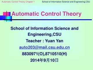
Which block scheme represents the level control depicted in the picture below? LC • Define servo and control problem.
Fout Which block schemes represents the level control depicted in the picture? hdesired Fin h + Controller Tank withliquid - FIn hdesired Fout h + Controller Tank with liquid - hdesired Fout FIn + Controller Tank withliquid - h [Default] [MC Any] [MC All] h hdesired Fin Fout + Controller Tank with liquid -
Group Task 1 [Dorf, Ch. 1, E1.10] Unmanned aerial vehicles (UAV’s) are being developed to operate in the air autonomously for long periods of time. By autonomous, we mean that there is no interaction with human ground controllers. Sketch a block diagram on an autonomous UAV that is tasked for crop monitoring and that must fly a pre-specified trajectory as accurately as possible. Label all of the blocks with both specific and general terms. Define servo and (one possible) control problem.
Group Task 1 [Dorf, Ch. 1, E1.10 – Example of realworldsolution] Wind Possibleanswer :
Group Task 1 [Dorf, Ch. 1, E1.10] Example of realworldsolution (without disturbances) Exercise: Addsignals!
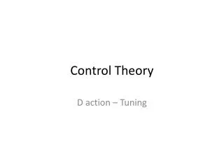
Watch out! PO = (25-23.75)/(23.75-10) * 100 = approx. 10%
Group Task 2 • For a pressurecontrolproblem, a controller is requiredwith the followingspecificationsfor the controlproblem: • For a unit step change of the disturbance • the steady state errorshouldbelessthan 0.3 bar; • the percentage overshoot has to be smaller than 20%; • the 4% settling time shouldbe smaller than 5 seconds. • Assumingyouuse a controller thatjustmeets these specifications, make a plot of the CV with respect to time, assumingthat the CV is constant and equal to 10 bar whensuddenly a step of sizeone is applied to the disturbance at t=5s.
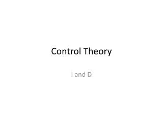
Group Task 3 [basedonDorf P1.11] Tank 1 • Discuss the workingprinciple of this water clock. • Whichvariable is the controlledvariablez(t)? • Draw the blockscheme of the feedback loop. • What does the referencetrajectory r(t) look like? • Whatwill the process input u(t)ideally look like? • Define a possibledisturbance and show howitmightinfluence the correct working of the water clock. Tank 2 Tank 3
Group Task 3 F23 F12 h2,desired h3 h2 Tank 2 + Opening2 Float Tank 3 - Disturbances entering the system behind the feedback loop willnotberesolved. Example: evaporation of water in tank 3.